Advertisement
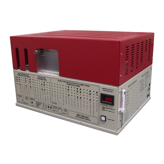
Installation of the Vacuum Pump Interface on the
SRI 8610C GC
Remove the six Phillips head
screws holding the bottom of the
GC.
Tilt the GC on its back and remove
the bottom cover. Disconnect the
ground wire so the bottom cover
can be moved out of the way.
Important:
Disconnect the AC
power cord
SRI Tech Support 310-214-5092
December 2009
Page 1
www.srigc.com
Advertisement
Table of Contents

Related Manuals for Sri 8610C GC


Summary of Contents for Sri 8610C GC
- Page 1 Installation of the Vacuum Pump Interface on the SRI 8610C GC Remove the six Phillips head screws holding the bottom of the Tilt the GC on its back and remove the bottom cover. Disconnect the ground wire so the bottom cover can be moved out of the way.
- Page 2 Installation of the Vacuum Pump Interface on the SRI 8610C GC The Vacuum Pump Interface Kit 8670-0073 contains: Vacuum pump (specify voltage) Solid state Relay (100-240 volts AC ) and attached screws 2 amp fuse and fuseholder 250volts 4 #6 x 1/2” screws...
- Page 3 Installation of the Vacuum Pump Interface on the SRI 8610C GC Mount the solid state relay module on the aluminum plate next to the fan. Mark the hole locations and then drill two 5/32” holes. Use two of the screws and lock- nuts to secure the solid state relay module.
- Page 4 Installation of the Vacuum Pump Interface on the SRI 8610C GC Crimp the black wire to a ring ter- minal and then screw it to Termi- nal#1 on the Solid state Relay. Cut the fuseholder wire about 3 inches from the fuse.
- Page 5 Installation of the Vacuum Pump Interface on the SRI 8610C GC Crimp the yellow and green/yellow wires in the ring terminals. Con- nect the yellow to terminal#3 and the green/yellow to terminal#4. Snap the plastic cover over the solid state relay module.
- Page 6 Installation of the Vacuum Pump Interface on the SRI 8610C GC Run the fuseholder wire, the white wire and .5meter long length of the green/yellow wire out through the hole in the chassis. Slide a sec- tion of heat shrink tubing onto each wire before soldering to the power jack.
- Page 7 Installation of the Vacuum Pump Interface on the SRI 8610C GC Crimp the two green/yellow wires ( from solid state relay and from power jack ) to a single ring termi- nal and then connect the ring ter- minal to the chassis ground stud with a lockwasher.
- Page 8 Installation of the Vacuum Pump Interface on the SRI 8610C GC Connect the white and black wires (white from power jack ), ( black from soild state relay ) to the third and fourth terminals from the left on the display board. There will already be a white and black wire inserted into these terminals.
- Page 9 Installation of the Vacuum Pump Interface on the SRI 8610C GC Label the Relay Function table on the right side of the GC with the Relay letter ( A-H ) to which you assigned the Vacuum Pump Inter- face .
Need help?
Do you have a question about the 8610C GC and is the answer not in the manual?
Questions and answers