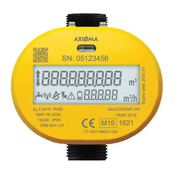
AXIOMA METERING UAB QALCOSONIC W1 Technical Description, Installation Manual And User Manual
Ultrasonic water meter
Hide thumbs
Also See for QALCOSONIC W1:
Summary of Contents for AXIOMA METERING UAB QALCOSONIC W1
- Page 1 AXIOMA METERING UAB ULTRASONIC WATER METER QALCOSONIC W1 TECHNICAL DESCRIPTION, INSTALLATION MANUAL AND USER GUIDE PL_QW1_V02...
-
Page 2: Table Of Contents
Turinys SAFETY INFORMATION ....................4 APPLICATION FIELD ........................4 TECHNICAL DATA ........................6 OPERATING PRINCIPLE ......................9 MARKING AND SEALING ......................9 Marking ............................9 Sealing ............................. 9 INSTALATTION ........................... 9 OPERATION ..........................10 VERIFICATION .......................... 14 TRANSPORTATION AND STORAGE REQUIREMENTS ............14 Annex A ............................. - Page 3 EU DECLARATION OF CONFORMITY AXIOMA Metering UAB, Kulautuvos g. 45a, LT-47190 Kaunas, Lietuva / Lithuania, hereby declares that the water meter QALCOSONIC W1 conforms to the essential requirements of the following Directives: 2014/32/EU Directive 2014/32/EU of the European Parliament and of the Council of 26 February...
-
Page 4: Safety Information
-25°C...70 °C (drained flow part) Storage and transportation temperature: APPLICATION FIELD Ultrasonic water meter QALCOSONIC W1 is desighed for measurement of cold and hot water consumption. The meter corresponds to essential requirements of the Technical Regulation requirements Annexes I and MI 001. - Page 5 Ordering code combination of the meter *: - - - - Meter QALCOSONIC W1 Type The ratio R (Q Code Permanent flow Overall length L, mm End connections Code rate Q G ¾ G ¾ G ¾ G ¾ G ¾...
-
Page 6: Technical Data
TECHNICAL DATA Ratio of the permanent flow rate to the lower limit of the flow-rate (selectable by the user): 250 , Q 315, Q 400, Q 800 The technical data of the meter are provided in Table 1.1. 1.1. - Page 7 Volume measurement unit’s Resolution of a displaying device 0,001 m Displaying range 999999,999 m The maximum permissible error (MPE), on volumes delivered at flow rate between the transitional flow rate Q (included) and the overload flow rate Q (included) is: ...
- Page 8 - RF 433 MHz - RF 915 MHz The data can be transmitted using the following protocols: - W-M-Bus T1; - W-M-Bus S1; - W-M-Bus-C1; - SIGFOX; - LORA WAN; Additional interface: M-Bus interface (galvanically isolated, communication time is limited Wired pulse output (galvanically isolated, pulse duration is limited)
-
Page 9: Operating Principle
OPERATING PRINCIPLE The flow measuring principle is based on ultrasonic measurement method. The ultrasonic signal along the measuring section moves many times before, and the flow downstream between the ultrasonic sensors have to perform transmitter and receiver functions. From the resulting time difference the flow rate is calculated and indicated in display Water meter performs all necessary measurement and data storage functions. -
Page 10: Operation
Mounting The temperature of the working environment should not be higher than 70 No special requirements are established for the free space around the meter. It is important that nearby installations or structures do not rest against the housing of the meter and do not interfere with reading the data from the display. - Page 11 The symbol is shown when there is a significant meter operation error (due to which the summing- up of volume and normal working time is stopped). For the Info code, see the LCD menu item 1.12 (Paragraph „Menu structure“). Menu structure Menu structure in normal mode is presented in Fig.
- Page 12 Forward flow volume Reverse flow volume Water temperature value Date Real - time Info code and error occurrence date Changes each 1 second Accumulated volume on set day /date Segment test Changes each 1 second ftm/h 1.10 User identification number 1.11 Control number The indication of irrelevant parameters can be turned off.
- Page 13 Viewing the readings in verification (test) mode Menu structure in verification ( test) mode is presented in the Fig 6.2 Fig. 6.2. Menu structure in verification (test) mode Volume readings in verification mode Parameter Value (example) Remark High-resolution integrated Updated every 10 second. volume Flow-rate value and inscription „tESt“...
-
Page 14: Verification
C - corresponds errors 8 + 4 D - corresponds errors 8 + 4 + 1 E - corresponds errors 8 + 4 + 2 F - corresponds errors 8 + 4 + 2 +1 Verification (test) mode control In verification (test) mode it is possible to achieve precise results within short measuring time. In the test mode, the meter: indicates the increased resolution of flow values;... -
Page 15: Annex A
Annex A Sizes and dimensions of water meter QALCOSONIC W1 A.1 DN 20: Model L, mm DN20 L105 DN20 L110 DN20 L130 DN20 L165 DN20 L190 PL WQ1_180829... - Page 16 A.2 DN 15: Model L, mm DN15 L80 DN15 L105 DN15 L 110 DN15 L165 DN15 L170 PL WQ1_180829...
-
Page 17: Annex B
Annex B Example of s ealing of water meter after installation PL WQ1_180829... -
Page 18: Warranty
Warranty period - 12 months from bringing into operation, but not more than 18 months from manufacturing date. Manufacturer’s address: UAB Axioma Metering UAB, Kulautuvos g. 45a, Kaunas LT-47190, Lithuania tel. +370 37 360234; fax. +370 37 360358. PL WQ1_180829...


Need help?
Do you have a question about the QALCOSONIC W1 and is the answer not in the manual?
Questions and answers