Sign In
Upload
Download
Table of Contents
Contents
Add to my manuals
Delete from my manuals
Share
URL of this page:
HTML Link:
Bookmark this page
Add
Manual will be automatically added to "My Manuals"
Print this page
×
Bookmark added
×
Added to my manuals
Manuals
Brands
Kjellberg Manuals
Welding System
PerCut 200
Short instruction manual
Kjellberg PerCut 200 Short Instruction Manual
Hide thumbs
1
2
3
4
5
6
7
8
9
10
11
12
13
14
15
16
17
18
Table Of Contents
19
20
21
22
23
24
25
26
27
28
29
30
31
32
33
34
35
36
37
38
39
40
41
42
43
44
45
46
47
48
49
50
51
52
53
54
55
56
57
58
59
60
61
62
63
64
65
66
67
68
69
70
71
72
73
74
75
76
77
78
79
80
81
82
83
84
85
86
87
88
89
90
91
92
93
94
95
96
97
98
99
100
101
102
103
104
105
106
107
108
109
110
111
112
113
114
115
116
117
118
119
120
121
122
123
124
125
126
127
128
129
130
131
132
133
134
135
136
137
138
139
140
141
142
143
144
145
146
147
148
149
150
151
152
153
154
155
156
157
158
159
160
161
162
163
164
165
166
167
168
169
170
171
172
173
174
175
176
177
178
179
180
181
182
183
184
185
186
page
of
186
Go
/
186
Contents
Table of Contents
Troubleshooting
Bookmarks
Table of Contents
Table of Contents
1 General Information
Warranty Claim
Standards and Directives
Information to the Instruction Manual - Target Groups
Plasma Cutting as Procedure
2 Safety Instructions
Explanation of the Safety Symbols
Endangerment by High Contact Voltage
Working in Environments with Increased Electric Endangerment
Endangerment by High Voltage Ignition
Endangerment by Electromagnetic Fields
Endangerment by Heat and Light Radiation
Endangerment by Gases, Smoke and Types of Dust
Prevention of Formation of Oxyhydrogen
Endangerment by Noise
Endangerment by Spatter
Handling of Pressure Reducer
Handling of the Coolant "Kjellfrost
3 Maintenance
Maintenance General
Intervals of Maintenance
Cleaning
Cleaning of the Power Source
Cleaning of the Gas Supply
Electrical Revision
Plasma Torch
Maintenance Special
Gas Pressure Test
Coolant System
Preventive Periodic Maintenance - Component Change Plan
4 Customer Information on Repair Processing
5 Disposal
Disposal of the Packing Material
Disposal of the Units after Decommissioning
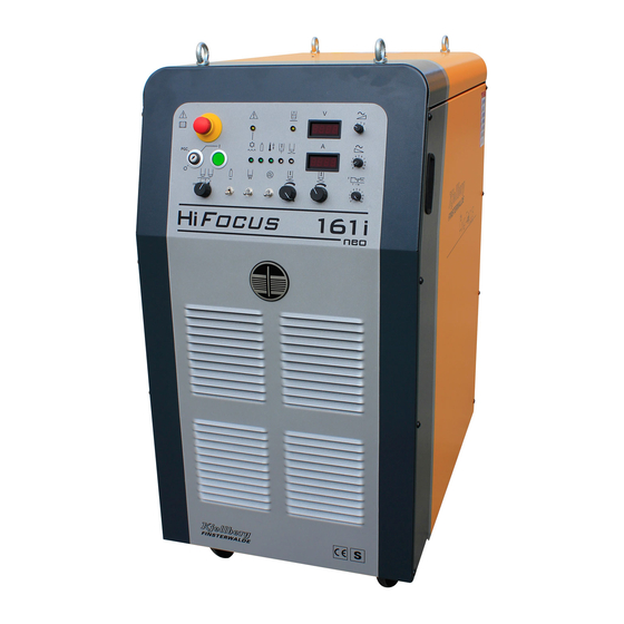
6 Power Source Hifocus 161I Neo
Technical Data
Technical Description
Setup
Hifocus- Technology
Electronic Control
Special Parameters of the Power Source
Cutting Technology
Plasma Marking
Putting into Operation
Check, Placement and Transport
Installation
Mains Connection
Workpiece Connection / Current Return Line
Connections at the Rear Panel of the Power Source
Remote Control FB
Filling up the Coolant
Operating and Display Elements
Cutting Operation
Combination of the Hifocus with CNC-Controls of the Guiding Systems and Robots
Multiple Machine Operation
Switching Regime of the Power Source
Start by Remote Control FB (at Commissioning)
Start by CNC
Start from CNC with Special Function "Separate Ignition Signal
Start from CNC with Special Function "Pre-Impulse
Protective Facilities
Information for Trouble Shooting
7 Plasma Gas Control Unit PGE 3-161
Technical Data
Technical Description
Connection of the Plasma Gas Control Unit
Operating and Display Elements
Connection of the Gas Hoses between Plasma Gas Console and PBA
Connection of the Gas Supply
Plasma Gases
Swirl Gases
8 Plasma Machine Torch Percut 200 / 210
Technical Data
Technical Description
Connection of the Plasma Torch to the Plasma Torch Connection Unit PBA
Consumables and Their Exchange
Plasma Machine Torch Percut 200 / 210A / 210M
Replacement of the Current Socket and Current Plug in the Torch Shaft
Operation of the Torch after Consumable Change
Information for Using of the Change Heads
Dismantling of the Change Head
Maintenance of the Change Head
Control of the O-Rings
Control of the Location Pin
Add on of the Change Heads
Percut 210A
Percut 210M
Maintenance and Attendance of the Plasma Torch
9 Plasma Machine Torch Percut 201 / 211
Technical Data
Technical Description
Connection of the Plasma Torch to the Plasma Torch Connection Unit PBA
Consumables and Their Exchange
Plasma Machine Torch Percut 201 / 211A / 211M
Replacement of the Current Socket and Current Plug in the Torch Shaft
Operation of the Torch after Consumable Change
Information for Using of the Change Heads
Dismantling of the Change Head
Maintenance of the Change Head
Control of the O-Rings
Control of the Location Pin
Add on of the Change Heads
Dpercut 211A
Percut 211M
Maintenance and Attendance of the Plasma Torch
10 Plasma Torch Connection Unit PBA-161
Technical Data
Technical Description
Connection of the Plasma Torch Connection Unit
11 Wiring Diagrams
12 Spare Parts Lists
Spare Parts List Hifocus 161I
Spare Parts Lists PGE 3-161
Spare Parts List Percut 200
Spare Parts List Percut 210M
Spare Parts List Percut 201
Spare Parts List Percut 211A
Spare Parts List Percut 211M
Spare Parts List PBA-161
13 List of Abbreviations
14 Index
Advertisement
Quick Links
Download this manual
Short Instruction Manual
Short instruction manual HiFocus 161i with PGE 3-161
- Saftety
- Consumable change of the plasma torch
- Cutting charts
Art.-Nr.: .11.034.902.KBA
Table of
Contents
Previous
Page
Next
Page
1
2
3
4
5
Advertisement
Table of Contents
Need help?
Do you have a question about the PerCut 200 and is the answer not in the manual?
Ask a question
Questions and answers
Related Manuals for Kjellberg PerCut 200
Welding System Kjellberg FineFocus Flash 101 Instruction Manual
Power source, plasma machine torch (79 pages)
Welding System Kjellberg SmartFocus 300 Short Instruction Manual
(186 pages)
Welding System Kjellberg FineFocus 800 Instruction Manual
Plasma cutting unit with swirl-gas torch for dry and under water cutting, suitable for cnc controlled cutting systems (64 pages)
Welding System Kjellberg CUTi 70 Instruction Manual
Cuti 70 (46 pages)
This manual is also suitable for:
Percut 210a
Percut 210m
Percut 201
Percut 211a
Percut 211m
Pba-161
...
Show all
Pge 3-161
Hifocus 161i neo
Hifocus 161i
Finefocus hifocus 130 neo
Table of Contents
Save PDF
Print
Rename the bookmark
Delete bookmark?
Delete from my manuals?
Login
Sign In
OR
Sign in with Facebook
Sign in with Google
Upload manual
Upload from disk
Upload from URL


Need help?
Do you have a question about the PerCut 200 and is the answer not in the manual?
Questions and answers