
Related Manuals for Kjellberg FineFocus Flash 101


Summary of Contents for Kjellberg FineFocus Flash 101
- Page 1 Instruction Manual - Power source CutFire 100i - Plasma machine torch Flash 101 G/L Art.-No.: .11.034.812BA Pos : 1 /Allgemei nes/C opyright und Inhal ts verzeic hnis @ 0\mod_1197373477322_19.doc x @ 1421 @ @ 1...
- Page 2 All rights reserved in the event of the grant of a patent, utility model or design. Subject to alterations Kjellberg Finsterwalde Plasma und Maschinen GmbH, 2017 Kjellberg Finsterwalde Plasma und Maschinen GmbH Oscar-Kjellberg-Straße 20 DE - 03238 Finsterwalde Tel.:...
-
Page 3: Table Of Contents
General information Contents General information ..........................5 Warranty claim ........................... 5 Standards and Directives ........................5 Information to the instruction manual - target groups ................ 6 Plasma cutting as procedure ......................7 Safety instructions ..........................9 Explanation of the safety symbols ..................... 9 Endangerment by high contact voltage ................... - Page 4 General information Remote control FB (optional) ......................39 Operating and display elements ...................... 39 6.10 Cutting operation ..........................42 6.11 Combination of the power source with CNC-controls of the guiding systems and robots ....46 6.12 Start regime CutFire ........................48 6.12.1 Start by remote control FB (at commissioning) ...............
-
Page 5: General Information
Pos : 3.3 /Allgemei nes/Gewährl eistungs ans pruch @ 0\mod_1197458588902_19.doc x @ 1520 @ @ 1 We point out explicitly that only spare parts and consumables of Kjellberg original have to be used! Otherwise a warranty claim does not exist. Kjellberg Finsterwalde as manufacturer of the equipment can not make any guarantees for the safety of the equipment according to the valid regulations. -
Page 6: Information To The Instruction Manual - Target Groups
General information Pos : 3.7 /Ü bers chriften/1.1/Hinweis e z ur Berti ebsanlei tung - Zielgruppen @ 0\mod_1197551942124_19.doc x @ 1656 @ 2 @ 1 1.3 Information to the instruction manual - target groups Pos : 3.8 /Allgemei nes/Hinweis e z ur Betri ebsanleitung @ 0\mod_1198075112816_19.doc x @ 2238 @ @ 1 Our products are of first-rate quality and high reliability and are in operational condition at any time. -
Page 7: Plasma Cutting As Procedure
General information Pos : 5.1 /Ü bers chriften/1.1/Plas masc hneiden als Verfahren @ 0 \mod_1197554221573_19.doc x @ 1704 @ 2 @ 1 Plasma cutting as procedure Pos : 5.2 /Allgemei nes/Pl as masc hneidverfahren, Beschr eibung @ 0\mod_1198075619387_19.doc x @ 2248 @ @ 1 The plasma is defined as a gas having atoms and molecules which are partly split into ions and electrons and having therefore a high electrically conductivity. - Page 8 General information Pos : 5.5 /Allgemei nes/Pl as masc hneidverfahren,T abelle @ 2\mod_1238069850087_19.doc x @ 9805 @ @ 1 Plasma cutting process Dry-plasma cutting Under water-plasma cutting without swirl gas with swirl gas with swirl gas A Coolant circuit B Plasma gas C Swirl gas In plasma cutting without Plasma torches with swirl gas...
-
Page 9: Safety Instructions
Safety instructions Pos : 7.1 /Ü bers chriften/1/Sicherheit @ 0\mod_1197388764940_19.doc x @ 1439 @ 1 @ 1 2 Safety instructions Pos : 7.2 /Ü bers chriften/1.1/Erläuter ung der Sic herheitss ymbole @ 0\mod_1197465551735_19.doc x @ 1537 @ 2 @ 1 Explanation of the safety symbols Pos : 7.3 /Sicherheit/Erläuterung der Symbol e @ 0 \mod_1197465063600_19.doc x @ 1533 @ @ 1 DANGER, WARNING and CAUTION are signal words, which describes a degree of exposure. - Page 10 Safety instructions Warning symbols (choice): A black graphic symbol within a yellow triangle with a black edge defines a safety sign, which describes an endangerment. Warning of general hazard area Warning of dangerous electrical voltage! Warning of flammable substances Warning of explosive substances Warning of poisonous substances Warning of optical radiation Warning of electromagnetic radiation...
- Page 11 Safety instructions Mandatory sign (choice): A white graphic symbol within a blue circle defines a safety sign, which indicates that an action shall be carried out, in order to prevent an endangerment. General mandatory sign Use eye shield Use ear protection Use inhalation protection Use foot guard Use hand guard...
- Page 12 Safety instructions Prohibition sign (choice): A black graphic symbol within a red circle with a red diagonal bar defines a safety sign, which indicates that an action shall be stopped or not be carried out. Smoking is forbidden Fire, open light and smoking are forbidden Contact is forbidden Meal and drinking are forbidden Do not use in housing areas...
- Page 13 Safety instructions Pos : 7.5 /Sicherheit/Warnschil d, Text @ 0 \mod_1199715950375_19.doc x @ 2404 @ @ 1 Warning label The warning label is visibly attached on the power source. The operator and the maintenance personnel must familiarize themselves with the meaning of the symbols before working at the unit.
- Page 14 Safety instructions Pos : 7.8 /Sicherheit/Weitere Hinweise und War nungen @ 0\mod_1199797455150_19.doc x @ 2420 @ @ 1 Further information and warning: to ensure stableness of the plasma unit, an inclination of 10° may not be exceeded connect the power source only with properly fitted protective conductor ...
-
Page 15: Endangerment By High Contact Voltage
Safety instructions Pos : 7.10 /Übersc hriften/1.1/Gefähr dung durc h hohe Ber ühr ungss pannung @ 0 \mod_1197552041125_19.doc x @ 1660 @ 2 @ 1 2.2 Endangerment by high contact voltage Pos : 7.11 /War nung, Vorsic ht, Ver bot, Gebot, Hinweis/Warnung ( orange) / Rettungsz eichen (grün) /Warnung Öffnen des Gerätes @ 0\mod_1199714392778_19.doc x @ 2391 @ @ 1 WARNING Warning of dangerous electric voltage Electric shock can be deadly. -
Page 16: Endangerment By High Voltage Ignition
Safety instructions Pos : 7.19 /Übersc hriften/1.1/Gefähr dung durc h H oc hspannungszündung @ 0\mod_1197552347357_19.doc x @ 1668 @ 2 @ 1 2.4 Endangerment by high voltage ignition Pos : 7.20 /Sic herheit/Gefährdung durch Hochs pannungsz ündung @ 0\mod_1199798211923_19.doc x @ 2428 @ @ 1 For igniting the pilot arc a high voltage igniter is installed in the power source. -
Page 17: Endangerment By Electromagnetic Fields
Safety instructions Pos : 7.24 /Übersc hriften/1.1/Gefähr dung durc h elektromagnetisc he Stör ung en @ 0\mod_1197552428045_19.doc x @ 1672 @ 2 @ 1 2.5 Endangerment by electromagnetic fields Pos : 7.25 /Sic herheit/Gefährdung durch el ektr omag netische Störungen-Teil 1 @ 0\mod_1199798656080_19.doc x @ 2436 @ @ 1 The plasma cutting installation complies with the instructions of the EN 60974-10 (VDE 0544, part 10) "Arc Welding Equipment –... -
Page 18: Endangerment By Heat And Light Radiation
Safety instructions Pos : 7.31 /Sic herheit/Gefährdung durch el ektr omag netische Störungen-Teil 4 @ 0\mod_1199799007142_19.doc x @ 2448 @ @ 1 Recommendations of methods to minimize disturbances If disturbances are detected it may be necessary to carry out further precautions, such as those: ... -
Page 19: Endangerment By Gases, Smoke And Types Of Dust
Safety instructions Pos : 7.39 /Übersc hriften/1.1/Gefähr dung durc h Gas e, Rauc he und Stäube @ 0\mod_1197552640467_19.doc x @ 1680 @ 2 @ 1 Endangerment by gases, smoke and types of dust Pos : 7.40 /Sic herheit/Gefährdung durch Gas e, R auche und Stäube @ 0\mod_1199799715379_19.doc x @ 2456 @ @ 1 Due to the plasma process itself hazardous substances may be produced. - Page 20 Safety instructions Pos : 7.48 /Sic herheit/Plas masc hnei den i n Ver bindung mit Wass er @ 0 \mod_1199800260679_19.doc x @ 2468 @ @ 1 If you use process gases, which contains hydrogen,for plasma cutting in connection with water, there may lead to formation of highly explosive oxyhydrogen.
-
Page 21: Endangerment By Noise
Safety instructions Pos : 7.51 /Übersc hriften/1.1/Gefähr dung durc h Lär m @ 0\mod_1197552995672_19.doc x @ 1688 @ 2 @ 1 2.9 Endangerment by noise Pos : 7.52 /Sic herheit/Gefährdung durch Lär m-Teil 1 @ 0\mod_1199800350921_19.doc x @ 2473 @ @ 1 Be aware that during the plasma cutting a high noise level is produced. -
Page 22: Endangerment By Spatter
Safety instructions Pos : 7.57 /Übersc hriften/1.1/Gefähr dung durc h Spritz er @ 0\mod_1197553139562_19.doc x @ 1692 @ 2 @ 1 2.10 Endangerment by spatter Pos : 7.58 /Sic herheit/Gefährdung durch Sc hnei ds pritzer @ 0\mod_1199800700797_19.doc x @ 2481 @ @ 1 During plasma cutting and hole piercing sparks, slag and hot metal are produced. -
Page 23: Maintenance
Maintenance Pos : 9.1 /Ü bers chriften/1/Wartung @ 0 \mod_1197550754735_19.doc x @ 1640 @ 1 @ 1 3 Maintenance Pos : 9.2 /Warnung, Vorsicht, Verbot, Gebot, Hinweis/Warnung (orange) / R ettungszeic hen (grün)/War nung Öffnen des Ger ätes @ 0\mod_1199714392778_19.doc x @ 2391 @ @ 1 WARNING Warning of dangerous electric voltage Electric shock can be deadly. -
Page 24: Cleaning
Maintenance Pos : 9.7 /Ü bers chriften/1.1.1/R einigung @ 0 \mod_1197630016183_19.doc x @ 1764 @ 3 @ 1 3.1.2 Cleaning Pos : 9.8 /Ü bers chriften/1.1.1.1/R einigung der Stromq uell e @ 0 \mod_1216713725288_19.doc x @ 4955 @ 4 @ 1 3.1.2.1 Cleaning of the power source Pos : 9.9 /Wartung/R einigung der Str omq uell e @ 0 \mod_1197990338325_19.doc x @ 2134 @ @ 1... -
Page 25: Electrical Revision
Maintenance Pos : 9.13 /Übersc hriften/1.1.1/el ektrisc he Revi sion @ 0 \mod_1197630324394_19.doc x @ 1768 @ 3 @ 1 3.1.3 Electrical revision Pos : 9.14 /War nung, Vorsic ht, Ver bot, Gebot, Hinweis/Gebotsz eichen (bl au) /el ektrisc he Revi sion durc h Elektrofac hkraft @ 0\mod_1215496817737_19.doc x @ 4470 @ @ 1 The electrical revision of the plasma cutting system and the disposal of the noticed defects have to be carried out according to the statutory provisions via electrical specialist! Pos : 9.15 /Wartung/El ektrisc he Revi sion @ 0 \mod_1197990462046_19.doc x @ 2138 @ @ 1... -
Page 26: Plasma Torch
This refers specially to the torch head and the consumables. Pos : 9.20 /War nung, Vorsic ht, Ver bot, Gebot, Hinweis/Gebotsz eichen (bl au) /Original- Kjellberg-Vers chl eißteile @ 0\mod_1202913276255_19.doc x @ 3649 @ @ 1 You are only allowed to use ORIGINAL Kjellberg spare parts and consumables! The use of other manufacturer consumables leads to the loss of the warranty claim. -
Page 27: Customer Information On Repair Processing
Customer information on repair processing Pos : 11.1 /Übersc hriften/1/Reparaturen, Kundeni nfor mati onen z u @ 8\mod_1336998620141_19.doc x @ 154157 @ 1 @ 1 4 Customer information on repair processing Pos : 11.2 /Reparaturinfor mationen/Ei nleitung @ 8\mod_1336997520792_19.doc x @ 154101 @ @ 1 To ensure effective processing of repair orders, please take note of the following: Pos : 11.3 /War nung, Vorsic ht, Ver bot, Gebot, Hinweis/Hi nweis e (sc hwarz)/Reparaturinfo- 1-ohne Z ubehör @ 8\mod_1336994716980_19.doc x @ 154023 @ @ 1 Information... -
Page 28: Disposal
Pos : 13.5 /Entsorgung/Ents orgung der Ger äte @ 0 \mod_1214904040990_19.doc x @ 4389 @ @ 1 The units of the company Kjellberg Finsterwalde are products which can properly be recycled or disposed after placing out of operation on the basis of regional applicable regulations by a waste management company. -
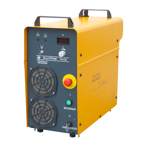
Page 29: Power Source Cutfire 100I
Power source CutFire 100i Pos : 15.1 /Stromquellen/C utFir e/C utFire100i/Bild CutFire 100i+Hintergrund @ 1\mod_1233310973656_19.doc x @ 8120 @ @ 1 Pos : 15.2 /Übersc hriften/1/CutFire 100i @ 1\mod_1233311055736_19.doc x @ 8125 @ 1 @ 1 6 Power source CutFire 100i - Power s ourc e CutFire 100i Pos : 15.3 /Steuermodul e/--------------- Seitenumbruc h --------------- @ 0\mod_1197390577023_19.doc x @ 1454 @ @ 1... -
Page 30: Technical Data
Power source CutFire 100i Pos : 15.4 /Übersc hriften/1.1/Technisc he Daten/T ec hnisc he D aten @ 0\mod_1197454101092_19.doc x @ 1496 @ 2 @ 1 6.1 Technical Data Pos : 15.5 /Stromquellen/C utFir e/C utFire100i/T ec hnis che D aten CutFire 100i @ 1\mod_1231743054568_19.doc x @ 7150 @ @ 1 primary side: mains voltage U 3~ +PE 400 V ±10 %, 50 Hz... -
Page 31: Technical Description
Pos : 15.8 /War nung, Vorsic ht, Ver bot, Gebot, Hinweis/Gebotsz eiche n (bl au) /Sic her hei tstec hnisc he Einheit/Pl as mabr enner Flas h 101 G/L nur für CutFire 100i, Stromquelle @ 16\mod_1494486529598_19.doc x @ 281920 @ @ 1 Only plasma torches of the type Flash 101 G/L of Kjellberg Finsterwalde are determined for use with power sources CutFire 100i by EN 60974-1. -
Page 32: Advantages And Features Of The Plasma Cutting Machine
Power source CutFire 100i Pos : 15.11 /Ü bersc hriften/1.1/Vor teil e und Eigenschaften @ 0\mod_1197631653563_19.doc x @ 1796 @ 2 @ 1 6.3 Advantages and features of the plasma cutting machine Pos : 15.12 /Str omquellen/C utFire/CutFire100i/T echnologisc he Vorteile @ 1\mod_1232370557139_19.doc x @ 7859 @ @ 1 Due to the extreme high energy density a number of technical advantages will be obtained: ... -
Page 33: Ranges Of Application
Power source CutFire 100i Pos : 15.18 /Ü bersc hriften/1.1/Anwendungsbereic he @ 0\mod_1197631891811_19.doc x @ 1800 @ 2 @ 1 Ranges of application Pos : 15.19 /Str omquellen/C utFire/CutFire100i/anwendungs ber eic h @ 1 \mod_1232377498796_19.doc x @ 7879 @ @ 1 The maximum cutting power of 16.6 kVA conveyed to the workpiece according to the principle of direct discharge, allows the cutting of electrically conductive materials up to a maximum thickness of 40 mm, depending on the type of material. -
Page 34: Plasma Marking, Plasma Notching, Plasma Punching
Power source CutFire 100i Pos : null /Übersc hriften/1.1/M ar kier en, Ker ben, Körnen @ 0\mod_1197632801813_19.doc x @ 1804 @ 2 @ 1 6.5 Plasma marking, Plasma notching, Plasma punching Pos : null /Str omquellen/C utFire/CutFire100i/Fl ash101/Mar ki eren, Kerben, Körnen - C utFire @ 16\mod_1496844259935_19.doc x @ 282453 @ @ 1 definition Plasma marking Marking of electrically conductive materials by means of plasma beam... -
Page 35: Putting Into Operation
Power source CutFire 100i Pos : 15.27 /Ü bersc hriften/1.1/Inbetriebnahme @ 0\mod_1197632842339_19.doc x @ 1808 @ 2 @ 1 6.6 Putting into operation Pos : 15.28 /Ü bersc hriften/1.1.1/Ü ber prüfung und Aufstellung @ 2\mod_1237299536187_19.doc x @ 9590 @ 3 @ 1 6.6.1 Check and placement Pos : 15.29 /Str omquellen/Allgemeines /Überpr üfung @ 0\mod_1201525234482_19.doc x @ 3250 @ @ 1... -
Page 36: Installation
Power source CutFire 100i Pos : 15.32 /Ü bersc hriften/1.1.1/Ins tall ation @ 0\mod_1197634429825_19.doc x @ 1870 @ 3 @ 1 6.6.2 Installation Pos : 15.33 /Ü bersc hriften/1.1.1.1/N etz ansc hluss @ 0\mod_1197634515572_19.doc x @ 1874 @ 4 @ 1 6.6.2.1 Mains connection Pos : 15.34 /Warnung, Vorsic ht, Verbot, Gebot, Hi nweis /War nung (or ang e) / R ettungszeic hen (grün)/Warnung Öffnen des Gerätes @ 0\mod_1199714392778_19.doc x @ 2391 @ @ 1... -
Page 37: Connection Of The Gas Supply
Power source CutFire 100i Pos : 15.44 /Ü bersc hriften/1.1/Anschl uss der Gas vers orgung @ 0\mod_1197636278356_19.doc x @ 1938 @ 2 @ 1 6.7 Connection of the gas supply Pos : 15.45 /Warnung, Vorsic ht, Verbot, Gebot, Hi nweis /Gebotszeic hen (blau)/Gas vers orgung-Druc kminder er @ 0\mod_1199803733989_19.doc x @ 2529 @ @ 1 For the gas supply only high- quality pressure regulators have to be used, guaranteeing a constant supply pressure. -
Page 38: Connections At The Rear Panel Of The Power Source
Power source CutFire 100i Pos : 15.53 /Ü bersc hriften/1.1.1.1/R üc kwand der Stromquelle @ 0\mod_1197634723247_19.doc x @ 1886 @ 4 @ 1 6.7.1.1 Connections at the rear panel of the power source Pos : 15.54 /Str omquellen/C utFire/CutFire100i/R üc ks eitige Anschl üss e der CutFire 100i @ 1\mod_1232453450571_19.doc x @ 7936 @ @ 1 All cables, control lines and the plasma torch will be connected to the rear panel of the power source. -
Page 39: Remote Control Fb (Optional)
Power source CutFire 100i Pos : 15.58 /Ü bersc hriften/1.1/F ernbedi ensatz @ 0 \mod_1197633349787_19.doc x @ 1820 @ 2 @ 1 6.8 Remote control FB (optional) Pos : 15.59 /Str omquellen/Allgemeines /Fer nbediens atz @ 0\mod_1201786336258_19.doc x @ 3384 @ @ 1 With the remote control FB the cutting process with the plasma machine torch (ignition of pilot arc) can be started and stopped. - Page 40 Power source CutFire 100i Pos : 15.63 /Str omquellen/C utFire/CutFire100i/Besc hr eibung Bedi en- und Anzeig eel emente @ 1\mod_1232456064537_19.doc x @ 7960 @ @ 1 - changeable filter pads made of metal (see maintenance) tumbler switch “gas test / machine torch operation” - upper position: Gas test ON - for adjusting the plasma gas pressure - for measuring the flow rate of plasma gas...
- Page 41 Power source CutFire 100i Pos : 15.65 /Str omquellen/C utFire/CutFire100i/Anz eige i m Di spl ay @ 4\mod_1275648139495_19.doc x @ 32530 @ @ 1 information at the Meaning Remark display Software version number (example: V 1.08) This will be displayed one after another Status (Initialisierung Stufe 2) for short time after the start.
-
Page 42: Cutting Operation
Power source CutFire 100i Pos : 15.67 /Ü bersc hriften/1.1/Sc hneidbetrieb @ 0\mod_1197633041208_19.doc x @ 1816 @ 2 @ 1 6.10 Cutting operation Pos : 15.68 /Warnung, Vorsic ht, Verbot, Gebot, Hi nweis /War nung (or ang e) / R ettungszeic hen (grün)/Plas maanl age nic ht mit geöffnetem Gehäus e betr eiben @ 0\mod_1201864736354_19.doc x @ 3502 @ @ 1 WARNING It is not allowed to operate the unit with any of the housing cover plates not in place! It is hazardous to the operator and other people in the area, and prevents the equipment from... - Page 43 Power source CutFire 100i Pos : 15.72 /Str omquellen/C utFire/CutFire100i/R eihenfolge der Bedienung @ 1\mod_1232457704078_19.doc x @ 7965 @ @ 1 Operation sequences Red emergency Unlocking (turn to left) button S3 “emergency Stop” (7) Turn to „I“ Turn key switch S1 - Mains voltage to control transformer “mains ON”...
- Page 44 Power source CutFire 100i Pos : 15.74 /Str omquellen/C utFire/CutFire100i/Ei n- und Aussc halten des Pl as mabr enners @ 2\mod_1234429147234_19.doc x @ 8555 @ @ 1 Switching On and OFF of the plasma torch The pilot arc will be established when pressing the ON-button of the remote control FB or by the ON-signal from the guiding system on (X102 (B2, B3)) after the gas preflow.
- Page 45 Power source CutFire 100i Pos : 15.82 /Str omquellen/C utFire/CutFire100i/Abbildung-Abstandsregel ung @ 2\mod_1236159880801_19.doc x @ 9281 @ @ 1 fig. 5: schematic diagram of a cutting process with height control system Pos : 15.83 /Str omquellen/C utFire/CutFire100i/Besc hr eibung Abstandsreg elung @ 2\mod_1236159882018_19.doc x @ 9286 @ @ 1 Sequence steps of height control process ON / lowering plasma torch to ignition height torch ON / gas pre-flow / waiting for pilot arc ON...
-
Page 46: Combination Of The Power Source With Cnc-Controls Of The Guiding Systems And Robots
The necessary plug (system Wieland) can be supplied on request from Kjellberg Finsterwalde. The potential-free contacts are dimensioned for a current load of max. 500 mA DC at a control voltage of 24 V. - Page 47 Power source CutFire 100i Pos : 15.87 /Warnung, Vorsic ht, Verbot, Gebot, Hi nweis /Hinweise (sc hwarz)/Betrei ben ohne N ot-Hal t-Kontakt ist nic ht möglich- X102 @ 0\mod_1201868128382_19.doc x @ 3522 @ @ 1 Information Before connecting the control cable remove the link X102 (C3-C4). It is not possible to operate the power source without the link or without emergency stop signal from the guiding system! Pos : 15.88 /Str omquellen/C utFire/CutFire100i/Spannung niemals an B 2 und B3 @ 1\mod_1232635023852_19.doc x @ 8064 @ @ 1...
-
Page 48: Start Regime Cutfire
Power source CutFire 100i Pos : 15.92 /Ü bersc hriften/1.1/Eins chaltregi me C utFire @ 2\mod_1236165121672_19.doc x @ 9301 @ 2 @ 1 6.12 Start regime CutFire Pos : 15.93 /Ü bersc hriften/1.1.1/Eins chaltung über F ernbedi ensatz @ 0 \mod_1197634911857_19.doc x @ 1894 @ 3 @ 1 6.12.1 Start by remote control FB (at commissioning) Pos : 15.94 /Str omquellen/HiFocus /HiFocus 280i/360i/440i/Ei nsc halten über F ernbedi ensatz @ 0 \mod_1201791128240_19.doc x @ 3451 @ @ 1 Connection to socket X132... -
Page 49: Protective Facilities
Power source CutFire 100i Pos : 15.100 /Ü bers chriften/1.1/Schutz einric htungen @ 0\mod_1197633842718_19.doc x @ 1840 @ 2 @ 1 6.13 Protective facilities Pos : 15.101 /Stromq uell en/CutFire/C utFire100i /Sc hutz einric htung @ 1\mod_1232636623437_19.doc x @ 8078 @ @ 1 The plasma cutting inverter is switched off by the following installations: ... -
Page 50: Information For Trouble Shooting
Power source CutFire 100i Pos : 15.103 /Ü bers chriften/1.1/Hinweis e z ur F ehl ersuche @ 0\mod_1197633890412_19.doc x @ 1844 @ 2 @ 1 6.14 Information for trouble shooting Pos : 15.104 /Warnung, Vorsicht, Ver bot, Gebot, Hinweis/Warnung ( orange) / R ettungsz eic hen (grün)/War nung Öffnen des Ger ätes @ 0\mod_1199714392778_19.doc x @ 2391 @ @ 1 WARNING Warning of dangerous electric voltage Electric shock can be deadly. - Page 51 Power source CutFire 100i Pos : 15.109 /Stromq uell en/CutFire/C utFire100i /Fehlerliste @ 2\mod_1234777921331_19.doc x @ 8600 @ @ 1 error chart / error codes - of the power source information Meaning reason end or rectification on the display error pilot arc pilot arc time exceeded - remote control: burning period...
- Page 52 Power source CutFire 100i information Meaning reason end or rectification on the display torch error general current workpiece current relay workpiece K1 switch OFF unit, current module current relay module 1 check torch and consumables current module current relay module analogue cap error torch cap not o.
-
Page 53: Plasma Machine Torch Flash 101 G/L
Plasma machine torch Flash 101 G/L Pos : 17.1 /Br enner/Flash100/Fl as h_101/Flas h 101 @ 16\mod_1494578424674_0.doc x @ 282083 @ @ 1 Pos : 17.2 /Übersc hriften/1/Br enner/Pl as ma-M asc hinenbr enner Flas h 101 @ 16\mod_1494487644212_19.doc x @ 281983 @ 1 @ 1 7 Plasma machine torch Flash 101 G/L - Plas ma mac hine torc h Flash 101 G/L... -
Page 54: Technical Data
Plasma machine torch Flash 101 G/L Pos : 17.4 /Übersc hriften/1.1/Technisc he Daten/T ec hnisc he D aten @ 0\mod_1197454101092_19.doc x @ 1496 @ 2 @ 1 7.1 Technical Data Pos : 17.5 /Br enner/Flash100/Fl as h_101/Technisc he Daten @ 16\mod_1494407903067_19.doc x @ 281573 @ @ 1 Flash 101 G/L Art.-No.: .11.844.701.106... -
Page 55: Technical Description
Pos : 17.8 /War nung, Vorsic ht, Ver bot, Gebot, Hinweis/Gebotsz eichen (bl au) /Sic her hei tstec hnisc he Einheit/Pl as mabr enner Flas h 1 01 G/L nur für CutFire 100i, Br enner @ 16\mod_1494486536774_19.doc x @ 281941 @ @ 1 The plasma torch Flash 101 G/L of Kjellberg Finsterwalde is determined for use with plasma inverter CutFire 100i by EN 60974-1. -
Page 56: Advantages And Features Of The Plasma Cutting Machine
Plasma machine torch Flash 101 G/L Pos : 17.11 /Ü bersc hriften/1.1/Vor teil e und Eigenschaften @ 0\mod_1197631653563_19.doc x @ 1796 @ 2 @ 1 7.3 Advantages and features of the plasma cutting machine Pos : 17.12 /Brenner/Flas h100/Fl ash_101/H auptmer kmale und Vorteile @ 16 \mod_1494422364905_19.doc x @ 281678 @ @ 1 ... -
Page 57: Putting Into Operation
Pos : 17.18 /Warnung, Vorsic ht, Verbot, Gebot, Hi nweis /Gebotszeic hen (blau)/Ser vic e Kjell berg + autorisi erte Firmen @ 1 \mod_1233670938905_19.doc x @ 8224 @ @ 1 The operating personal may change only consumables at the plasma torch! Repairs are only allowed by the service personal of the firm Kjellberg Finsterwalde and authorised companies. -
Page 58: Connection Of The Plasma Torch To The Plasma Unit
Plasma machine torch Flash 101 G/L Pos : 17.21 /Ü bersc hriften/1.1/Anschl uss des Plasmabrenners an die Anlage @ 1\mod_1233669536242_19.doc x @ 8206 @ 2 @ 1 7.5 Connection of the plasma torch to the plasma unit Pos : 17.22 /Brenner/Flas h100/Ans chl uss Brenner an Anl age @ 1\mod_1233656644152_19.doc x @ 8166 @ @ 1 The torch lock cap must be unlocked with the included special wrench. -
Page 59: Consumables And Their Exchange
Plasma machine torch Flash 101 G/L Pos : 17.26 /Ü bersc hriften/1.1/Vers chl eißteile und deren Aus tausc h @ 0\mod_1197635517862_19.doc x @ 1914 @ 2 @ 1 7.6 Consumables and their exchange Pos : 17.27 /Warnung, Vorsic ht, Verbot, Gebot, Hi nweis /War nung (or ang e) / R ettungszeic hen (grün)/Versc hl eißteilwec hsel am Pl as mabrenner - Plas maanl age von N etz trennen @ 0\mod_1200055457147_19.doc x @ 2774 @ @ 1 WARNING In order to change consumables, the plasma cutting system shall be switched OFF and secured against any accidental start. - Page 60 Plasma machine torch Flash 101 G/L Pos : 17.33 /Brenner/Flas h100/Fl ash_101/Vers chl eißteil-Übersic ht Flas h101G/L @ 16\mod_1494425286159_19.doc x @ 281741 @ @ 1 cooling tube cathode insulating element gas guide nozzle protection cap spatter protection swirl gas cap fig.
-
Page 61: Accessories
Plasma machine torch Flash 101 G/L Dismounting of used consumables Unscrew the protection cap (0x.06). (if necessary screw off the spatter protection (0x.07) and the swirl gas cap (0x.08) from the protection cap (0x.06).) Pull off the nozzle (0x.05) manually or press out of protection cap (0x.06). Pull off the gas guide (0x.04) and the insulating element (0x.03) manually. - Page 62 Plasma machine torch Flash 101 G/L for CutFire 100i 2 pcs. cathode 2 pcs. gas guide 1 pcs. nozzle 0,6 mm (35 A) 1 pcs. nozzle 0,7 mm (45 A) 1 pcs. nozzle 1,2 mm(65 A) 1 pcs. nozzle 1,4 mm (100 A) 1 pcs.
-
Page 63: Wiring Diagrams
Wiring diagrams Pos : 19.1 /Übersc hriften/1/Sc haltpl äne @ 0\mod_1215503515361_19.doc x @ 4489 @ 1 @ 1 8 Wiring diagrams Pos : 19.2 /Anl agen/Sc haltpläne/Cutfire/D ec kbl att CutFire 100i @ 2\mod_1234963259791_19.doc x @ 8630 @ @ 1 for the plasma cutting machine CutFire 100i drawing no. - Page 64 Wiring diagrams Pos : 19.4 /Anl agen/Sc haltpläne/Cutfire/Str omlaufplan C utFir e 100i @ 2 \mod_1234431513122_19.doc x @ 8561 @ @ 1 Pos : 19.5 /Steuermodul e/--------------- Seitenumbruc h --------------- @ 0\mod_1197390577023_19.doc x @ 1454 @ @ 1...
- Page 65 Wiring diagrams Pos : 19.6 /Anl agen/Sc haltpläne/Cutfire/C NC-Sc hnittstelle @ 2\mod_1234962983222_19.doc x @ 8620 @ @ 1 Pos : 20 /Steuermodul e/--------------- Seitenumbruc h --------------- @ 0\mod_1197390577023_19.doc x @ 1454 @ @ 1...
-
Page 66: Spare Parts Lists
Dear customer, with the plasma cutting system you have purchased a quality product from the Kjellberg Finsterwalde Plasma und Maschinen GmbH. When ordering spare parts, please mention the complete article no. of the torch and also the complete designation with article no. of the spare parts according to this list. -
Page 67: Spare Parts List Cutfire 100I
Spare parts lists Pos : 21.4 /Übersc hriften/1.1/Ers atz teillisten/Stromquelle/Ers atzteilliste C utFire 100i @ 2\mod_1236248852082_19.doc x @ 9362 @ 2 @ 1 9.1 Spare parts list CutFire 100i Pos : 21.5 /Anl agen/Ers atz teiliste/C utFir e/ETL_C utFire100i @ 2\mod_1236247235117_19.doc x @ 9336 @ @ 1 .11.034.812 15.06.2017 article no. - Page 68 Spare parts lists .11.034.812 15.06.2017 article no. designation code pcs. 03.00 .16.500.371 Control Unit 03.01 .10.161.722.230 Contactor BF65 00 223-230V 50/60Hz 1,00 03.02 .10.190.031 Filter 3x470n/10n 1,00 03.03 .10.189.300 Fuse holder 6,3x32 500V (F1-F5) 5,00 03.04 .10.189.302 Fuse cap 6,3 x 32 mm (F1-F5) 5,00 03.05...
- Page 69 Spare parts lists .11.034.812 15.06.2017 article no. designation code pcs. 05.00 .16.500.506 Power module 05.01 .10.535.601 Fan Type W2S130-AA03-44 Dm.150 M1,M2 2,00 05.04 .10.105.868 Module SKD 62/16 1,00 05.05 .10.123.261 PTC Resistor 60°C 3,00 05.06 .11.412.102.450 Choke module 100 A 2,00 05.07 .10.535.605...
- Page 70 Spare parts lists Pos : 21.7 /Anl agen/Ers atz teiliste/C utFir e/et-Frontwand @ 2\mod_1237285080522_19.doc x @ 9534 @ @ 1 fig. 11: front panel of the CutFire 100i Pos : 21.8 /Steuermodul e/--------------- Seitenumbruc h --------------- @ 0\mod_1197390577023_19.doc x @ 1454 @ @ 1...
- Page 71 Spare parts lists Pos : 21.9 /Anl agen/Ers atz teiliste/C utFir e/et-Rüc kwand @ 2\mod_1237285146144_19.doc x @ 9538 @ @ 1 Fig. 12: rear panel of the CutFire 100i Pos : 21.10 /Steuer module/--------------- Seitenumbr uc h --------------- @ 0\mod_1197390577023_19.doc x @ 1454 @ @ 1...
- Page 72 Spare parts lists Pos : 21.11 /Anlagen/Ers atzteiliste/C utFire/et-Steuerei nheit @ 2\mod_1237285250438_19.doc x @ 9542 @ @ 1 Fig. 13: control unit of the CutFire 100i Pos : 21.12 /Steuer module/--------------- Seitenumbr uc h --------------- @ 0\mod_1197390577023_19.doc x @ 1454 @ @ 1...
- Page 73 Spare parts lists Pos : 21.13 /Anlagen/Ers atzteiliste/C utFire/et-Sei tenansic ht @ 2\mod_1237285330695_19.doc x @ 9546 @ @ 1 Fig. 14: side view of the CutFire 100i Pos : 21.14 /Steuer module/--------------- Seitenumbr uc h --------------- @ 0\mod_1197390577023_19.doc x @ 1454 @ @ 1...
- Page 74 Spare parts lists Pos : 21.15 /Anlagen/Ers atzteiliste/C utFire/et-Leistungs modul @ 2\mod_1237285465586_19.doc x @ 9550 @ @ 1 Fig. 15: power module of the CutFire 100i Pos : 21.16 /Steuer module/--------------- Seitenumbr uc h --------------- @ 0\mod_1197390577023_19.doc x @ 1454 @ @ 1...
-
Page 75: Spare Parts Lists Flash 101 G/L
Spare parts lists Pos : 21.17 /Ü bersc hriften/1.1/Ersatzteillisten/Brenner/Ersatzteilliste Flas h 101 G/L @ 16 \mod_1494911984536_19.doc x @ 282204 @ 2 @ 1 9.2 Spare parts lists Flash 101 G/L Pos : 21.18 /Anlagen/Ers atzteiliste/C utFire/ET L_Flas h101G/L @ 16\mod_1494579018073_19.doc x @ 282104 @ @ 1 .11.844.701.E0 15.05.2017 article no. - Page 76 Spare parts lists .11.844.701.E0 15.05.2017 article no. designation code pcs. 02.00 .16.500.508 Consumables standard 02.01 .11.844.701.142 cooling tube I912 02.02 .11.844.711.350 cathode I015 02.03 .11.844.701.150 insulator - I100 02.04 .11.844.721.145 gas guide I121 02.05 .11.844.701.412 nozzle I2512 02.05 .11.844.701.414 nozzle I2514 02.06 .11.844.701.160 protection cap I302...
- Page 77 Spare parts lists Pos : 21.20 /Anlagen/Ers atzteiliste/C utFire/ET-Ü bersic ht-Fl ash101 @ 16\mod_1494850239930_19.doc x @ 282133 @ @ 1 Fig. 16: Flash 101 G/L Pos : 22 /Steuermodul e/--------------- Seitenumbruc h --------------- @ 0\mod_1197390577023_19.doc x @ 1454 @ @ 1...
-
Page 78: Index
Index Pos : 23.1 /Übersc hriften/1/Stichwortverzeic hnis - Index @ 0\mod_1197627852821_19.doc x @ 1748 @ 1 @ 1 10 Index Pos : 23.2 /Steuermodul e/--------------- Wechs el ein- auf z weis pal tig --------------- @ 0\mod_1197627993609_19.doc x @ 1752 @ @ 1 Pos : 23.3 /Allgemeines /Stic hwortverzeic hni s - Index @ 0\mod_1197627514230_19.doc x @ 1740 @ @ 1 accessories ............ - Page 79 Index Trouble shooting ..........50 Wiring diagrams ..........63 Warranty claim ............5 Workpiece connection........36 === Ende der Liste für T extmar ke Inhalt ===...
Need help?
Do you have a question about the FineFocus Flash 101 and is the answer not in the manual?
Questions and answers