
Related Manuals for Kjellberg CUTi 70


Summary of Contents for Kjellberg CUTi 70
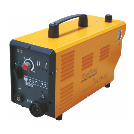
- Page 1 Instruction manual - Power source CUTi 70 - Plasma torch PHT-31 G/L art.-no.: .11.035.402.BA Stand: 2009-03-24 BA2009-008...
- Page 2 All rights reserved in the event of the grant of a patent, utility model or design. Subject to alterations . © Kjellberg Finsterwalde Plasma und Maschinen GmbH, 2009 Kjellberg Finsterwalde Plasma und Maschinen GmbH Leipziger Str. 82 DE - 03238 Finsterwalde Tel.:...
-
Page 3: Table Of Contents
Connection of gas supply....................28 5.5.3 Operation ..........................29 5.5.3.1 Control and display elements ..................29 5.5.3.2 Switching ON the CUTi 70 ....................30 5.5.3.3 Switching OFF the CUTi 70....................30 Cutting operation ..........................30 Protective installations........................31 Trouble shooting..........................31... - Page 4 Plasma hand torch PHT-31 G/L......................32 Technical data ..........................32 Technical description ........................32 Main features and advantages....................... 33 range of application ........................33 Commissioning ..........................34 6.5.1 Connection of the hand torch to the plasma unit..............34 6.5.2 Cutting operation ........................35 6.5.2.1 Cutting start and ignition of pilot arc ................
-
Page 5: General Information
Pos: 3.3 /Allgemeines/Gewährleistungsanspruch @ 0\mod_1197458588902_6.doc @ 1518 We point out explicitly that only spare parts and consumables of Kjellberg origin have to be used! Otherwise a warranty claim does not exist. Kjellberg as manufacturer of the equipment can not make any guarantees for the safety of the equipment according to the valid regulations. -
Page 6: Information To The Instruction Manual - Target Groups
Pos: 3.7 /Überschriften/1.1/Hinweise zur Bertiebsanleitung - Zielgruppen @ 0\mod_1197551942124_6.doc @ 1654 1.3 Information to the instruction manual - target groups Pos: 3.8 /Allgemeines/Hinweise zur Betriebsanleitung @ 0\mod_1198075112816_6.doc @ 2236 Our products are of first-rate quality and high reliability and are in operational condition at any time. You fully will enjoy all these benefits, as long as you carefully observe these instructions for operation, maintenance and handling. -
Page 7: Principle Of Dry Plasma Cutting Without Swirl Gas
Pos: 5.1 /Überschriften/1.1/Plasmaschneiden als Verfahren @ 0\mod_1197554221573_6.doc @ 1702 1.4 Principle of dry plasma cutting without swirl gas Pos: 5.2 /Allgemeines/Plasmaschneiden als Verfahren @ 0\mod_1198075619387_6.doc @ 2246 Pos: 5.5 /Überschriften/1.1.1/Trocken-Plasmaschneiden @ 0\mod_1197554596042_6.doc @ 1710 Pos: 5.6 /Überschriften/1.1.1.1/Trocken-Plasmaschneiden ohne Sekundärmedium @ 0\mod_1197554835210_6.doc @ 1718 Pos: 5.7 /Allgemeines/Trockenplasmaschneiden ohne Sekundärmedium @ 0\mod_1199708913662_6.doc @ 2352 Pos: 5.8 /Allgemeines/Prinzipdarstellung Plasmaschneiden ohne Sekundärmedium @ 0\mod_1199709444902_6.doc @ 2356 1 Pilot resistor... -
Page 8: Safety Instructions
Pos: 7.1 /Überschriften/1/Sicherheit @ 0\mod_1197388764940_6.doc @ 1437 2 Safety instructions Pos: 7.2 /Überschriften/1.1/Erläuterung der Sicherheitssymbole @ 0\mod_1197465551735_6.doc @ 1535 2.1 Explanation of the safety symbols Pos: 7.3 /Sicherheit/Erläuterung der Symbole @ 0\mod_1197465063600_6.doc @ 1531 DANGER, WARNING and CAUTION are signal words, which describes a degree of exposure. DANGER DANGER describes an endangerment with a high degree of risk, when it is not avoided, it results in death or a severe injury. - Page 9 Warning symbols (choice): A black graphic symbol within a yellow triangle with a black edge defines a safety sign, which describes an endangerment. Warning of general hazard area Warning of dangerous electrical voltage! Warning of flammable substances Warning of explosive substances Warning of poisonous substances Warning of optical radiation Warning of electromagnetic radiation...
- Page 10 Mandatory sign (choice): A white graphic symbol within a blue circle defines a safety sign, which indicates that an action shall be carried out, in order to prevent an endangerment. General mandatory sign Use eye shield Use ear protection Use inhalation protection Use foot guard Use hand guard Use protective clothing...
- Page 11 Prohibition sign (choice): A black graphic symbol within a red circle with a red diagonal bar defines a safety sign, which indicates that an action shall be stopped or not be carried out. Smoking is forbidden Fire, open light and smoking are forbidden Contact is forbidden Meal and drinking are forbidden Do not use in housing areas...
- Page 12 Pos: 7.5 /Sicherheit/Warnschild, Text @ 0\mod_1199715950375_6.doc @ 2402 Information and warning: Pos: 7.6 /Sicherheit/Warnschild, Bild und Beschreibung @ 0\mod_1199716068148_6.doc @ 2406 1. The operator and the maintenance personnel must read and understand the instruction manual as well as learning the operation of the unit before work with it to avoid endangerments. The safety regulations of the respective company have to be taken into account.
-
Page 13: Endangerment By High Contact Voltage
Pos: 7.10 /Überschriften/1.1/Gefährdung durch hohe Berührungsspannung @ 0\mod_1197552041125_6.doc @ 1658 2.2 Endangerment by high contact voltage Pos: 7.11 /Warnung, Vorsicht, Verbot, Gebot, Hinweis/Warnung (orange) / Rettungszeichen (grün)/Warnung Öffnen des Gerätes @ 0\mod_1199714392778_6.doc @ 2389 WARNING Warning of dangerous electric voltage Electric shock can be deadly. -
Page 14: Endangerment By High Voltage Ignition
Pos: 7.17 /Überschriften/1.1/Gefährdung durch Hochspannungszündung @ 0\mod_1197552347357_6.doc @ 1666 2.4 Endangerment by high voltage ignition Pos: 7.18 /Sicherheit/Gefährdung durch Hochspannungszündung @ 0\mod_1199798211923_6.doc @ 2426 Pos: 7.18 /Sicherheit/Gefährdung durch Hochspannungszündung @ 0\mod_1199798211923_19.doc @ 2428 For igniting the pilot arc a high voltage igniter is installed in the power source. When pressing the ON-button the high voltage is applied to the cathode and nozzle. -
Page 15: Endangerment By Electromagnetic Fields
Pos: 7.22 /Überschriften/1.1/Gefährdung durch elektromagnetische Störungen @ 0\mod_1197552428045_6.doc @ 1670 2.5 Endangerment by electromagnetic fields Pos: 7.23 /Sicherheit/Gefährdung durch elektromagnetische Störungen-Teil1 @ 0\mod_1199798656080_6.doc @ 2434 Pos: 7.23 /Sicherheit/Gefährdung durch elektromagnetische Störungen-Teil1 @ 0\mod_1199798656080_19.doc @ 2436 The plasma cutting installation complies with the instructions of the EN 60974-10 (VDE 0544, part 10) "Arc Welding Equipment –... -
Page 16: Endangerment By Heat And Light Radiation
Pos: 7.29 /Sicherheit/Gefährdung durch elektromagnetische Störungen-Teil4 @ 0\mod_1199799007142_6.doc @ 2446 Recommendations of methods to minimize disturbances If disturbances are detected it may be necessary to carry out further precautions, such as those: • Filtering of the mains supply • Shielding the mains cable of the permanently installed plasma cutting (safe contact is necessary between shielding and housing) •... -
Page 17: Endangerments By Gases, Smoke And Types Of Dust
Pos: 7.35 /Überschriften/1.1/Gefährdung durch Gase, Rauche und Stäube @ 0\mod_1197552640467_6.doc @ 1678 2.7 Endangerments by gases, smoke and types of dust Pos: 7.36 /Sicherheit/Gefährdung durch Gase, Rauche und Stäube @ 0\mod_1199799715379_6.doc @ 2454 Pos: 7.36 /Sicherheit/Gefährdung durch Gase, Rauche und Stäube @ 0\mod_1199799715379_19.doc @ 2456 Due to the plasma process itself hazardous substances may be produced. -
Page 18: Endangerment By Noise
Pos: 7.44 /Sicherheit/Vermeidung von Knallgasbildung-Teil2 @ 0\mod_1199800260679_6.doc @ 2467 For water tables with level control Nitrogen has to be used instead of air for cutting of aluminium. Nitrogen with small purity is here sufficient. For water tables without level control it has to be ensured, that: •... -
Page 19: Endangerment By Spatter
Kjellberg. Furthermore the user has to follow local and national standards. Pos: 7.57 /Warnung, Vorsicht, Verbot, Gebot, Hinweis/Gebotszeichen (blau)/geltende nationale und lokale Vorschriften @ 0\mod_1199802901541_19.doc @ 2505 The operator has to follow national and local regulations (for example Employer’s Liability... -
Page 20: Maintenance
Pos: 9.1 /Überschriften/1/Wartung @ 0\mod_1197550754735_6.doc @ 1638 3 Maintenance Pos: 9.2 /Warnung, Vorsicht, Verbot, Gebot, Hinweis/Warnung (orange) / Rettungszeichen (grün)/Warnung Öffnen des Gerätes @ 0\mod_1199714392778_19.doc @ 2391 WARNING Warning of dangerous electric voltage Electric shock can be deadly. Further personal and material damages can result from impact. Before opening (for example error search) or starting any maintenance and repair work principally the power supply source has to be switched off and visibly disconnected from the mains. -
Page 21: Cleaning Of The Power Source
Pos: 9.7 /Überschriften/1.1.1/Reinigung @ 0\mod_1197630016183_6.doc @ 1762 3.1.2 Cleaning of the power source Pos: 9.9 /Wartung/Reinigung der Stromquelle @ 0\mod_1197990338325_19.doc @ 2134 From the power source all dust and dirt which has collected inside by the fan have to be removed in intervals of 4 to 6 months. -
Page 22: Plasma Torch
This refers specially to the torch head and the consumables. Pos: 9.20 /Warnung, Vorsicht, Verbot, Gebot, Hinweis/Gebotszeichen (blau)/Original-Kjellberg-Verschleißteile @ 0\mod_1202913276255_19.doc @ 3649 You are only allowed to use ORIGINAL Kjellberg spare parts and consumables! The use of other manufacturer consumables leads to the loss of the warranty claim. -
Page 23: Disposal
Pos: 11.5 /Entsorgung/Entsorgung der Geräte @ 0\mod_1214904040990_19.doc @ 4389 The units of the company Kjellberg Finsterwalde are products which can properly be recycled and disposed after placing out of operation on the basis of regional applicable regulations by a waste management company. -
Page 24: Power Source Cuti 70
5 Power source CUTi 70 5.1 Technical data CUTi 70 primary side: rotating current, 400 V +10/-10% 50/60 Hz input voltage U max. connecting load S 11,1 kVA power factor cos phi: 0,68 0,91 efficiency: main connection : voltage [V]... -
Page 25: Technical Description
• their is a consumable-kit for each plasma inverter (see the corresponding chapter ”accessories” at the instruction manual of the plasma torch) All modules of the CUTi 70 are placed in a portable housing. The control and display elements are placed at the front panel. -
Page 26: Ranges Of Application
5.4 Ranges of application Mild steels, high-alloyed steels, nonferrous metals (e.g. aluminium), and special alloys can be cut. Air is used as plasma gas. The plasma torches can be used for flying cutting and hole piercing. Straight, bevel, contour, and position cuts can be carried out as well as fusion drilling. In this manner, semi- finished products such as sheet metal, pipes, profiles, metal blanks, forged and formed parts, sheet stacks, scrap products, and castings can be thermally separated or processed. -
Page 27: Installation
5.5.2.1 Mains connection The CUTi 70 is equipped with a mains cable (4 x 2,5 mm , 3 m long) and a 16 A mains plug. The unit must be connected to the mains supply via a permanently installed socket. Mains fuses must be connected in series up to the current socket according to the table “Technical Data of the Plasma cutting... -
Page 28: Connection Of Gas Supply
Using unclean gases can lead to dual arcs, increased wear of the nozzles and cathodes, and damage the torch. The gas connection of the CUTi 70 is equipped with a filter pressure reducer to prevent soiling. 1 Adjusting knob to adjust the pressure of the plasma gas... -
Page 29: Operation
5.5.3 Operation 5.5.3.1 Control and display elements Fig. 5: control and display elements CUTi 70 (front panel) 1 mains switch S1 mains on - position 0: CUTi 70 “OFF” - position 1: CUTi 70 “ON” 2 signal lamp H1 green : - ON, mains voltage or mains switch ON 3 potentiometer “cutting current”... -
Page 30: Switching On The Cuti 70
By switching the mains switch S1 on the front panel to position 0, the system is switched off. When the CUTi 70 is not in use for a longer period of time, it is to be visibly unplugged from the mains. -
Page 31: Protective Installations
5.7 Protective installations The plasma cutting inverter is switched OFF by the following installations: • gas pressure monitoring if the gas pressure is < 0,4 MPa (4 bar) • temperature monitoring in case of thermal overload of the inverter The following protective installations protect the operator against high contact voltage: •... -
Page 32: Plasma Hand Torch Pht-31 G/L
Fig. 6: Technical data 6.2 Technical description The plasma torch of the type PHT-31 G/L of Kjellberg Finsterwalde are determined for use with power sources CUTi 70 by EN 60974-1. Only these Plasma torches and power sources are safety-related units in accordance with... -
Page 33: Main Features And Advantages
6.3 Main features and advantages • perform different procedures (see “range of application”) • quick and easy conversion by replacing the consumables of the plasma torch • recommended material-dependent range of material thickness from 25 mm, max.30 mm (separating cut) at a maximum cutting power of 70 A •... -
Page 34: Commissioning
The operating personal may change only consumables at the plasma torch! Repairs are only allowed by the service personal of the firm Kjellberg Finsterwalde and authorised companies. You are only allowed to use ORIGINAL Kjellberg spare parts and consumables! The use of other manufacturer consumables leads to the loss of the warranty claim. -
Page 35: Cutting Operation
6.5.2 Cutting operation WARNING Do not level the plasma torch towards the eyes or other parts of the body! Do not touch the nozzle, because there is an electrical hazard by the high voltage ignition and a risk of burns from the pilot arc! Avoid “flash burn”... -
Page 36: Cutting With Spacer Spring
6.5.2.3 Cutting with spacer spring The spacer spring guarantees a constant distance between the plasma torch and the workpiece. The spacer spring is inserted onto the spatter protector PHT-31 G/L Article-no. Designation .11.844.001.310 cathode PHT-31 G/L .11.844.001.153 gas guide PHT-31 G/L .11.844.001.410 nozzle 1,0 ( 50 A) N2210 .11.844.001.412... -
Page 37: Cutting With Bevelling Cap
6.5.2.5 Cutting with bevelling cap This method is advantageous for defined angular cutting, e.g. for preparing welding seams. PHT-31 G/L Article-no. Designation .11.844.001.310 cathode PHT-31 G/L .11.844.001.153 gas guide PHT-31 G/L .11.844.001.410 nozzle 1,0 (max. 50 A) N2210 .11.844.001.412 nozzle 1,2 (max. 70 A) N2212 .11.844.001.160 protection cap PHT-31 G/L .11.844.001.161... -
Page 38: Cutting With Bevelling Cutting Attachment
6.5.2.8 Cutting with bevelling cutting attachment The illustration shows the bevelling attachment (Art. No. 11.822.630) for trimming sheet metal and preparing welding seams. The bevelling attachment is guided manually and guarantees a constant distance with a fixed angle of inclination of the torch to the workpiece. The height and angle of inclination of the plasma torch to the workpiece can be adjusted continuously. -
Page 39: Consumables And Their Exchange
6.6 Consumables and their exchange WARNING In order to change consumables, the plasma cutting machine shall be switched OFF and secured against any accidental start. An unauthorised start-up is prevented by e.g. pulling out the key of the key-operated switch after switching off the plasma cutting unit! Under no circumstances pliers or other unsuitable tools have to be used for consumable change, they entail inevitably the damage of the consumables, for example burr formation and thereby malfunctions of the plasma torch. - Page 40 cathode 1.1 cathode (long) gas guide nozzle 3.1 nozzle (long) 3.2 gouging nozzle protection cap spatter protection spacer spring contact cap bevelling cap nozzle cap multiple wrench Fig. 18: consumables of the plasma hand torch PHT-31 G/L...
-
Page 41: Accessories
6.7 Accessories Required accessories are the multiple wrench for replacing wearing parts in the plasma torch, which is part of the wearing parts kit, and the gas hose. Consumable kit for PHT-31 G/L 3 pcs. cathode PHT-31 G/L 1 pcs. nozzle 1,0 mm (20 - 50 A) 3 pcs. -
Page 42: Wiring Diagrams
7 Wiring diagrams Pos: 17.3.2 /Anlagen/Schaltpläne/Cutfire/Deckblatt CutFire 100i @ 2\mod_1234963259791_6.doc @ 8629 for the plasma inverter CUTi 70 Wiring diagram of the power source .11.035.402.SP1 a Pos: 17.3.3 /--------------- Seitenumbruch --------------- @ 0\mod_1197390577023_6.doc @ 1452... -
Page 44: Spare Parts Lists
Dear customer, with the plasma cutting system you have purchased a quality product from the Kjellberg Finsterwalde Plasma und Maschinen GmbH. When ordering spare parts, please mention the complete article no. of the torch and also the complete designation with article no. of the spare parts according to this list. -
Page 45: Spare Parts List Pht-31 G/L
8.1 Spare parts list PHT-31 G/L Pos: 23.7.13 /Anlagen/Ersatzteiliste/HiFo80i,130,160i/ETL_PGE 3-HM @ 1\mod_1232102790926_6.doc @ 7671 .11.844.001.000E 23.03.2009 Article-no. Designation Code pcs. 00.00.00 .11.844.001.006 PHT-31 G/L 6m/70A Plasma Hand Torch 01.00.00 .11.844.001.190 Torch head PHT-31 G/L without components 02.04.01 .11.844.001.310 Cathode PHT-31 G/L 02.04.02 .11.844.004.310 Cathode long PHT-31 G/L... - Page 46 Fig. 19: Plasma torch PHT-31 G/L...
Need help?
Do you have a question about the CUTi 70 and is the answer not in the manual?
Questions and answers