Yaesu FT-2800M Technical Supplement
Hide thumbs
Also See for FT-2800M:
- Operatiing manual (60 pages) ,
- Brochure & specs (4 pages) ,
- Technical supplement (32 pages)
Table of Contents
Advertisement
Quick Links
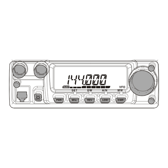
FM TRANSCEIVER
FT-2800M
Technical Supplement
©2007 VERTEX STANDARD CO., LTD.
Introduction
This manual provides technical information necessary for servicing the FT-2800M FM Transceiver.
Servicing this equipment requires expertise in handling surface-mount chip components. Attempts by non-qualified per-
sons to service this equipment may result in permanent damage not covered by the warranty, and may be illegal in some
countries.
Two PCB layout diagrams are provided for each double-sided circuit board in the Transceiver. Each side of is referred to
by the type of the majority of components installed on that side ("leaded" or "chip-only"). In most cases one side has only
chip components, and the other has either a mixture of both chip and leaded components (trimmers, coils, electrolytic
capacitors, ICs, etc.), or leaded components only.
While we believe the technical information in this manual to be correct, VERTEX STANDARD assumes no liability for
damage that may occur as a result of typographical or other errors that may be present. Your cooperation in pointing out
any inconsistencies in the technical information would be appreciated.
Specifications..................................................... 2
Exploded View & Miscellaneous Parts ........... 3
Block Diagram .................................................. 5
Circuit Description .......................................... 7
Alignment .......................................................... 9
EH014N90B
PWR
MHz
REV
LOW
Contents
Board Unit
μCOM Unit /RF Unit Circuit Diagram ......................... 13
μCOM Unit Parts Layout .............................................. 15
μCOM Unit Parts List ................................................... 19
RF Unit Parts Layout .................................................... 23
RF Unit Parts List ......................................................... 29
VERTEX STANDARD CO., LTD.
4-8-8 Nakameguro, Meguro-Ku, Tokyo 153-8644, Japan
VERTEX STANDARD
US Headquarters
10900 Walker Street, Cypress, CA 90630, U.S.A.
YAESU EUROPE B.V.
P.O. Box 75525, 1118 ZN Schiphol, The Netherlands
YAESU UK LTD.
Unit 12, Sun Valley Business Park, Winnall Close
Winchester, Hampshire, SO23 0LB, U.K.
VERTEX STANDARD HK LTD.
Unit 5, 20/F., Seaview Centre, 139-141 Hoi Bun Road,
Kwun Tong, Kowloon, Hong Kong
VERTEX STANDARD ( AUSTRALIA ) PTY., LTD.
Normanby Business Park, Unit 14/45 Normanby Road
Notting Hill 3168, Victoria, Australia
D/MR
(Schematics, Layouts & Parts)
1
Advertisement
Table of Contents

Related Manuals for Yaesu FT-2800M


Summary of Contents for Yaesu FT-2800M
-
Page 1: Table Of Contents
D/MR Introduction This manual provides technical information necessary for servicing the FT-2800M FM Transceiver. Servicing this equipment requires expertise in handling surface-mount chip components. Attempts by non-qualified per- sons to service this equipment may result in permanent damage not covered by the warranty, and may be illegal in some countries. -
Page 2: Specifications
Specifications General Frequency Range: Tx 144 - 146 MHz or 144 - 148 MHz Rx 144 - 146 MHz or 137 - 174 MHz Channel Step: 5/10/12.5/15/20/25/50/100 kHz Standard Repeater Shift: ±600 kHz Frequency Stability: Better than ±10 ppm [–4 °F to +140 °F (–20 °C to +60 °C)] Modes of Emission: F2/F3 Antenna Impedance:... -
Page 3: Exploded View & Miscellaneous Parts
Exploded View & Miscellaneous Parts S8002057 CASE-MAIN S8002055 PLATE-EARTH µCOM Unit S8002056 REFLECTOR S8002060 FILTER-LCD S8002061 CONNECT-LCD S8101435 CABLE S8101434 (with BLADE FUSE) S8002062 BUTTON S8002064 SPACER S8002059 CASE-FRONT S8101433 SPEAKER S8002052 RF ASSY KNOB-VOL S8002063 CAP-SP S8002052 KNOB-VOL S8101427 CONNECTOR S8002053 KNOB-DIAL... - Page 4 Exploded View & Miscellaneous Parts Note...
-
Page 5: Block Diagram
Block Diagram... - Page 6 Block Diagram Note...
-
Page 7: Circuit Description
Circuit Description Reception and transmission are switched by “RX” and The 2nd local in the IF-IC is produced from crystal X302 “TX” lines from the microprocessor unit (MPU). The re- (21.250 MHz), and the 1st IF is converted to 450 kHz by ceiver uses double-conversion superheterodyne circuitry, the 2nd mixer and stripped of unwanted components by with a 21.7 MHz 1st IF and 450 kHz 2nd IF. - Page 8 Circuit Description Transmitter RF output power from the final amplifier is sampled by C318 and C324 and is rectified by D302 (1SS321). The speech signal from the microphone is delivered via the MIC Jack to the RF Unit; after passing through Q315 The resulting DC is fed through Automatic Power Con- (NJM2902V) which consists of amplifier, pre-emphasis, troller Q309 (UMT1N), Q312 (DTC114), and Q311...
-
Page 9: Alignment
Alignment Introduction and Precautions Required Test Equipment The FT-2800M has been carefully aligned at the factory The following test equipment (and thorough familiarity for the specified performance at the 144 MHz amateur with its correct use) is necessary for complete realign- band. - Page 10 Entering the Alignment mode PLL VCO 1. Connect the DC voltmeter to TP-RVC on the RF Unit. Alignment of the FT-2800M is performed using a front- 2. Tune the frequency to 146.000 MHz. panel software-based procedure. To perform alignment 3. Adjust L330 on the RF Unit for 1.5 V on the DC volt- of the transceiver, it must first be placed in the “Align-...
- Page 11 Alignment 9. Inject a 146.050 MHz signal at a level of –5 dBμ (with TX Power Output 1 kHz modulation @ ±3.5 kHz deviation) from the (TXPW H/TXPW M/TXPW L2/TXPW L1) RF Signal Generator. 1. Tune the transceiver to 146.000 MHz, and set the 10.
- Page 12 Alignment TX Deviation (MODWFM/MODNFM) CTCSS TX Deviation (TONE W/TONE N) 1. Tune the transceiver to 146.000 MHz. 1. Tune the transceiver to 146.000 MHz. 2. Inject a 1 kHz audio tone at a level of 60 mV from the 2. Set the CTCSS tone to 100 Hz. Press and hold the [ MHz ] key for one second to Audio Generator.
-
Page 13: Μcom Unit /Rf Unit Circuit Diagram
μCOM Unit /RF Unit Circuit Diagram... - Page 14 μCOM Unit /RF Unit Circuit Diagram Note...
-
Page 15: Μcom Unit Parts Layout
μCOM Unit Parts Layout (Lot. 1 ~ 15) 2SJ144Y (VY) (Q101, 107, 135) 1SS302 (C3) NJM2902V (Q102) (D101, 102, 116, 118) DTC144EU (26) DAP202U (P) (Q103, 104, 130, 136, 137) (D104, 105) Side A NJM2904V (Q105) BU4094BCFV (Q106, 109) 2SC4617R (BR) (Q110, 111, 115, 130, 132) HD6473877H CAT24WC64JI... - Page 16 μCOM Unit Parts Layout (Lot. 16 ~ 57) 2SJ144Y (VY) R165 R166 (Q101, 107, 135) NJM2902V 1SS302 (C3) (Q102) (D101, 102, 116, 118) J110 DTC144EU (26) DAP202U (P) (Q103, 104, 130, 136, 137) (D104, 105) Side A NJM2904V (Q105) BU4094BCFV (Q106, 109) Q111 Q132...
- Page 17 μCOM Unit Parts Layout (Lot. 58 ~) 2SJ144Y (VY) (Q101, 107, 135) 1SS302 (C3) NJM2902V (Q102) (D101, 102, 116, 118) DTC144EU (26) DAP202U (P) (Q103, 104, 130, 136, 137) (D104, 105) Side A NJM2904V (Q105) BU4094BCFV (Q106, 109) 2SC4617R (BR) (Q110, 111, 115, 130, 132) HD6473877H CAT24WC64JI...
- Page 18 Note...
-
Page 19: Μcom Unit Parts List
μCOM Unit Parts List DESCRIPTION VALUE TOL. MFR'S DESIG VXSTD P/N VERS. LOT SIDE LAY ADR PCB with Components CS1806001 TYPE A2 CS1806002 TYPE A1 CS1806003 TYPE A3 CS1806004 TYPE B1 CS1806005 TYPE B2 CS1806006 TYPE B3 Printed Circuit Board S8101505 FR0142500 C 101... - Page 20 μCOM Unit Parts List DESCRIPTION VALUE TOL. MFR'S DESIG VXSTD P/N VERS. LOT SIDE LAY ADR D 110 19-215/Y2C-CN1P2/3T S8101644 D 110 19-213/Y2C/CN1P2/3T S8101669 D 111 19-215UYC/S530-A2/TR8 S8101421 D 111 19-215/Y2C-CN1P2/3T S8101644 D 111 19-213/Y2C/CN1P2/3T S8101669 D 112 19-215UYC/S530-A2/TR8 S8101421 D 112 19-215/Y2C-CN1P2/3T S8101644...
- Page 21 μCOM Unit Parts List DESCRIPTION VALUE TOL. MFR'S DESIG VXSTD P/N VERS. LOT SIDE LAY ADR R 119 CHIP RES. 1/16W RMC1/16 333JATP J24185333 R 120 CHIP RES. 1/16W RMC1/16 153JATP J24185153 R 121 CHIP RES. 1/16W RMC1/16 183JATP J24185183 R 122 CHIP RES.
- Page 22 μCOM Unit Parts List DESCRIPTION VALUE TOL. MFR'S DESIG VXSTD P/N VERS. LOT SIDE LAY ADR R 208 CHIP RES. 470k 1/16W RMC1/16 474JATP J24185474 R 209 CHIP RES. 470k 1/16W RMC1/16 474JATP J24185474 R 211 CHIP RES. 1/16W RMC1/16 103JATP J24185103 R 211 CHIP RES.
-
Page 23: Rf Unit Parts Layout
RF Unit Parts Layout (Lot. 1 ~ 15) 2SB1197K (AH) (Q303, 307) 2SC5006 (24) DTC144EU (26) (Q320, 322, 323) (Q304, 324) RD70HVF1 DTA114EU (14) (Q306) (Q325, 326) Side A... - Page 24 RF Unit Parts Layout (Lot. 1 ~ 15) 1SS312 (D302, 311) Side B...
- Page 25 RF Unit Parts Layout (Lot. 16 ~ 56) D301 2SB1197K (AH) C350 (Q303, 307) C333 C357 C323 L315 Q313 C555 R327 C554 C353 C315 2SC5006 (24) DTC144EU (26) (Q320, 322, 323) (Q304, 324) D304 L308 D303 D305 C346 RD70HVF1 DTA114EU (14) C372 C372 (Q306)
- Page 26 RF Unit Parts Layout (Lot. 16 ~ 56) C303 C309 M903 C324 C316 R330 R312 C328 R310 C320 C379 R340 R307 C334 L321 L323 Q317 R352 Q312 R356 R350 R323 R473 C395 R322 C347 Q309 C399 C338 R318 R500 C405 R423 R338 Q318...
- Page 27 RF Unit Parts Layout (Lot. 57 ~) 2SB1197K (AH) (Q303, 307) 2SC5006 (24) DTC144EU (26) (Q320, 322, 323) (Q304, 324) RD70HVF1 DTA114EU (14) (Q306) (Q325, 326) Side A...
- Page 28 RF Unit Parts Layout (Lot. 57 ~) 1SS312 (D302, 311) Side B...
-
Page 29: Rf Unit Parts List
RF Unit Parts List DESCRIPTION VALUE TOL. MFR'S DESIG VXSTD P/N VERS. LOT SIDE LAY ADR PCB with Components CS1805001 TYPE A2 CS1805002 TYPE A1 CS1805003 TYPE A3 CS1805005 TYPE B2 (CE) CS1805006 TYPE B3 CS1805007 TYPE B1 (CE) CS1805008 TYPE B1 Printed Circuit Board S8101505... - Page 30 RF Unit Parts List DESCRIPTION VALUE TOL. MFR'S DESIG VXSTD P/N VERS. LOT SIDE LAY ADR C 369 CHIP CAP. GRM1882C1H5R0CZ01D K22174206 C 369 CHIP CAP. GRM1882C1H5R0CZ01D K22174206 C 370 CHIP CAP. 100pF GRM1882C1H101JA01D K22174235 C 371 CHIP CAP. 0.001uF GRM188B11H102KA01D K22174821 C 372...
- Page 31 RF Unit Parts List DESCRIPTION VALUE TOL. MFR'S DESIG VXSTD P/N VERS. LOT SIDE LAY ADR C 452 CHIP CAP. 0.001uF GRM188B11H102KA01D K22174821 C 453 CHIP CAP. 0.1uF GRM188B11C104KA01D K22124805 C 454 AL.ELECTRO.CAP. UWT1H010MCL1GB K48170005 C 455 CHIP CAP. 12pF GRM1882C1H120JA01D K22174213 C 456...
- Page 32 RF Unit Parts List DESCRIPTION VALUE TOL. MFR'S DESIG VXSTD P/N VERS. LOT SIDE LAY ADR C 533 CHIP CAP. 33pF GRM1882C1H330JA01D K22174223 C 534 CHIP CAP. 0.001uF GRM188B11H102KA01D K22174821 C 535 AL.ELECTRO.CAP. 10uF EMV-160ADA100MD55G S8101398 C 537 CHIP CAP. GRM188B11A105KA61D S8101390 C 538...
- Page 33 RF Unit Parts List DESCRIPTION VALUE TOL. MFR'S DESIG VXSTD P/N VERS. LOT SIDE LAY ADR L 305 INDUCTOR 1.0PEW3.0D5.5T-E2 S8101405 L 306 INDUCTOR 1.0PEW2.5D1.5T S8101408 L 307 INDUCTOR 1.0PEW3.0D5.5T-E2 S8101405 L 308 INDUCTOR LAL03KH4R7K S8101413 L 310 INDUCTOR 1.0PEW3.0D5.5T-E2 S8101405 L 311 INDUCTOR...
- Page 34 RF Unit Parts List DESCRIPTION VALUE TOL. MFR'S DESIG VXSTD P/N VERS. LOT SIDE LAY ADR Q 337 LA4425A G1092241 Q 338 TRANSISTOR UMX2N TR G3070254 Q 344 TRANSISTOR DTC144EUA T106 G3070041 Q 345 TRANSISTOR DTC144EUA T106 G3070041 R 301 CHIP RES.
- Page 35 RF Unit Parts List DESCRIPTION VALUE TOL. MFR'S DESIG VXSTD P/N VERS. LOT SIDE LAY ADR R 365 CHIP RES. 1/16W RMC1/16 221JATP J24185221 R 366 CHIP RES. 1/16W RMC1/16 563JATP J24185563 R 367 CHIP RES. 1/16W RMC1/16 105JATP J24185105 R 369 CHIP RES.
- Page 36 RF Unit Parts List DESCRIPTION VALUE TOL. MFR'S DESIG VXSTD P/N VERS. LOT SIDE LAY ADR R 438 CHIP RES. 1/16W RMC1/16 123JATP J24185123 TYPE B3 R 439 CHIP RES. 1/16W RMC1/16 123JATP J24185123 TYPE B3 R 440 CHIP RES. 1.2k 1/16W RMC1/16 122JATP...
- Page 37 RF Unit Parts List DESCRIPTION VALUE TOL. MFR'S DESIG VXSTD P/N VERS. LOT SIDE LAY ADR R 516 CHIP RES. 1/16W RMC1/16 101JATP J24185101 R 517 CHIP RES. 2.2M 1/16W RMC1/16 225JATP J24185225 R 518 THERMISTOR TBPS1R473J475H5Q S8101388 R 519 CHIP RES.
- Page 38 Note DESCRIPTION VALUE TOL. MFR'S DESIG VXSTD P/N VERS. LOT SIDE LAY ADR...
- Page 40 Copyright 2007 VERTEX STANDARD CO., LTD. All rights reserved No portion of this manual may be reproduced without the permission of VERTEX STANDARD CO., LTD. Printed in Japan.
Need help?
Do you have a question about the FT-2800M and is the answer not in the manual?
Questions and answers