Honeywell VC Series Manual
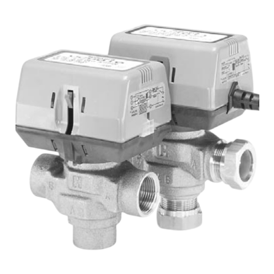
3-way balanced hydronic valves
Hide thumbs
Also See for VC Series:
- Installation instructions manual (10 pages) ,
- Installation manual (8 pages) ,
- Installation instructions manual (22 pages)
Advertisement
Quick Links
These two position 3 way hydronic valves are intended for use in a
normal indoor environment to control the flow of hot and/or cold water,
or glycol solution to 50% concentration.
They consist of an actuator, valve and replaceable valve cartridge
assembly. These valves can be piped for either diverting or mixing
valve applications in central heating and/or cooling systems; or for
individual fan coil, radiator or convector applications.
Depending on the model selected they can be controlled by either a
low or line voltage SPST OR SPDT controller such as a room
thermostat, aquastat or flow switch.
The specifiatons follwing are nominal and conform to generally
accepted industry standards. Honeywell is not responsible for
damages resulting from misapplications or misuse of its products.
Voltage:
Colour coded label
24V 50Hz; 24V 60Hz Models
100-130V 50-60Hz Model
200-240V 50-60Hz Model
Power consumption :
6 Watts Max. at nominal Voltages(during valve position change)
Use 24 V Class 2 transformer. Provide 6 VA for transformer and
connection wire sizing.
Maximum duty cycle: 15 %
End switch rating :
2.2 A inductive from 5 to 110 Vac,
1.0 A inductive above 110 to 277 Vac.
Min. DC switching capability: 5 mA @ 24 Vdc
Nominal timing :
Valve opens in 6 seconds @ 60Hz (20% longer @ 50 Hz)
Electrical termination : Available in 2 versions,
(1) Molex™ (header # 39-30-1060). Requires mating connector
(receptacle/housing # 39-01-2060). OR
(2) With integral 1 meter [nominal 39"] leadwire cable.
Operating ambient temperature : 0 to 65°C [32 to 150°F]
Shipping & storage temperature:
-40 to +65 °C [-40 to +150°F]
Atmosphere: non-corrosive, non-explosive
Min. & max. fluid temperatures: 1° to 95°C [34°to 203°F].
(Short duration peak: 120°C [248°F])
Operating pressure differential : Max. - 4 Bar [60 psi ]
Pressure rating : Static - 20 Bar [300 psi]
Burst - 100 Bar [1500 psi]
Valve material: Body of bronze; cartridge of Ryton™ (polyphenylene
sulphide) & Noryl™ (polyphenylene oxide); O-ring seals of EPDM
rubber; stainless steel stem.
Dimensions / pipe fitting sizes / flow ratings (nominal Cv):
See Diagram.
2003.03.04 © Honeywell Limited.
3 - Way, Balanced Hydronic Valves
SPECIFICATIONS
Blue
Black
Red
Nominal dimensions in mm and inches
Dimensions
Pipe Fitting Sizes
3/8" FLARE (no adapter)
1/2" SWEAT
1/2" FLARE (no adapter)
1/2" INVERTED FLARE (no adapter)
1/2" BSPP (int.), 15 MM Comp.
1/2" BSPT (int.)
1/2" NPT (int.)
3/4" BSPP (int.)
3/4" BSPT (int.)
3/4" BSPP (ext.)
3/4" NPT (int.)
3/4" SWEAT
22 MM* Compression
1" BSPP (int.)
1" BSPP (ext.),
1"BSPT(int.)
1" NPT (int.)
1" SWEAT
28 MM* Compression
* Includes compression nuts and olives
VC SERIES
C
D
Cv (nominal)
mm Inches mm Inches 6000 6100
98
3 -7/8
136 5-11/32
3.0
98
3 -7/8
136 5-11/32
4.2
3 -7/8
136 5-11/32
4.0
98
3 -7/8
136 5-11/32
4.2
98
3 -7/8
136 5-11/32
4.0
98
3 -7/8
136 5-11/32
4.0
98
3 -7/8
136 5-11/32
4.0
98
94 3-11/16 130 5-3/32
8.2
94 3-11/16 130 5-3/32
8.2
94 3-11/16 130 5-3/32
8.0
94 3-11/16 130 5-3/32
8.6
94 3-11/16 132 5-3/16
7.5
112 4-7/16 140
5-1/2
8.3
94 3-11/16 136 5-11/32
9.0
94 3-11/16 136 5-11/32
9.0
94 3-11/16 136 5-11/32
9.0
94 3-11/16 136 5-11/32
9.0
94 3-11/16 136 5-11/32
9.0
116 4-9/16 147 5-13/16
9.0
Form No. 95C-10647-4
2.7
3.8
3.8
4.2
3.7
3.8
3.7
6.9
6.2
6.7
6.6
5.9
6.9
7.5
7.9
8.1
8.6
6.6
7.5
Advertisement

Related Manuals for Honeywell VC Series


Summary of Contents for Honeywell VC Series
-
Page 1: Specifications
SPST OR SPDT controller such as a room thermostat, aquastat or flow switch. SPECIFICATIONS The specifiatons follwing are nominal and conform to generally accepted industry standards. Honeywell is not responsible for damages resulting from misapplications or misuse of its products. Voltage: Colour coded label 24V 50Hz;... - Page 2 Flow: Bottom port is marked AB. End ports are marked A & B. Port A is PLUMBING closed and port B open with the stem up position (Figure 1). Flow can IMPORTANT: be A or B to AB for mixing, or AB to A or B for diverting. Do not use boiler additives, solder flux and wetted materials which are petroleum based or contain mineral oil, hydrocar...
- Page 3 COMPRESSION MODELS WIRING For compression fitted models, tighten the compression nuts enough NOTE: Each 3-wire (SPDT) actuator must have individual SPDT controller. to make a watertight seal. TAKE CARE NOT TO OVER TIGHTEN. Maximum torque limit is 33 ft-lb for the 22 mm compression fitting, Use series 40 or 80 for single controller to control multiple valves.
- Page 4 Printed in Canada By using this Honeywell literature, you agree that Honeywell will have no liability for any damages arising out of your use or modification to, the literature. You will defend and indemnify Honeywell, its affiliates and subsidiaries, from and against any liability, cost, or damages, including attorneys’ fees, arising out of, or resulting from, any modification to the literature by you.
Need help?
Do you have a question about the VC Series and is the answer not in the manual?
Questions and answers