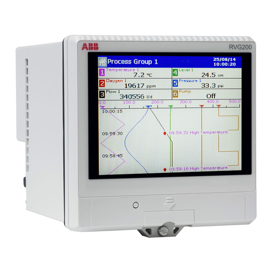
ABB ScreenMaster RVG200 Commissioning Instructions
Paperless recorder
Hide thumbs
Also See for ScreenMaster RVG200:
- Operating instructions manual (190 pages) ,
- Manual (17 pages) ,
- Battery replacement procedure (4 pages)
Table of Contents
Advertisement
Quick Links
Download this manual
See also:
Manual
Commissioning instructions CI/RVG200–EN
ScreenMaster RVG200
Paperless recorder
Measurement made easy
Introduction
This publication provides the following commissioning instructions
for the ScreenMaster RVG200 paperless recorder:
–
1 Locating the recorder
(location requirements)
–
2 Panel-mounting the recorder
(installation requirements to achieve IP66 / NEMA 4X
hose-down rating)
–
3 Electrical connections
(AC and DC min. / max. values and fuse requirements)
–
4 Navigation
(navigating the user-interface quickly and effectively)
–
5 Menus overview
(menu familiarization)
–
6 Basic setup
(steps required for first-time use)
–
7 Symbols and icons
(a schedule of icons / warning symbols that may be
displayed during operation)
For more information
Further publications for the ScreenMaster RVG200 paperless
recorder are available for free download from
links and reference numbers below) or by scanning this code:
RVG200 paperless recorder
Operating instructions
RVG200 paperless recorder
Datasheet
www.abb.com
(see
search for or click on:
OI/RVG200-EN
DS/RVG200-EN
Advertisement
Table of Contents

Related Manuals for ABB ScreenMaster RVG200


Summary of Contents for ABB ScreenMaster RVG200
- Page 1 Paperless recorder Measurement made easy Introduction For more information This publication provides the following commissioning instructions Further publications for the ScreenMaster RVG200 paperless for the ScreenMaster RVG200 paperless recorder: recorder are available for free download from www.abb.com (see links and reference numbers below) or by scanning this code: –...
-
Page 2: Health And Safety
Health & Safety Safety precautions Be sure to read, understand and follow the instructions contained within this manual before and during use of the equipment. Failure to do so could result in bodily harm or damage to the equipment. Warning. Installation and maintenance of this product must only be conducted by personnel authorized to work on electrical installations and in accordance with relevant local regulations. -
Page 3: Specification
Currently, monitoring and control instruments do not fall within the scope of the RoHS Directive, however ABB has taken the decision to adopt the recommendations in the Directive as the target for all future product design and component purchasing. -
Page 4: Panel-Mounting The Recorder
Locating the recorder Panel-mounting the recorder Referring to Fig. 2: Warning. 1. Cut the correct sized hole in the panel. Locate the recorder in a position where its temperature and humidity specification are not be exceeded, and 2. Insert recorder into the panel cut-out. -
Page 5: Electrical Connections
Electrical connections Warning. Note. Always route signal leads and power cables separately, The recorder is not fitted with a switch therefore a preferably in earthed (grounded) metal conduit. disconnecting device such as a switch or circuit breaker conforming to local safety standards must be fitted to ... -
Page 6: Power Supply Connections
Accessing the recorder connection terminals Power supply connections Referring to Fig. 3: Referring to Fig. 4: 1. Press the terminal cover release plate in recess 1. Make connections to the power supply terminals pull terminal cover away from the recorder body to (module position E) as follows: expose the terminal connections. - Page 7 Analog input / relay / hybrid connections Notes. Tighten terminal screws to a torque of 0.1 Nm (0.9 lbf.in). Analog inputs: 3-Lead RTD: 3-leads must have equal resistance, not exceeding 20 each – – for mA input types, to ensure loop continuity when the recorder is switched off, fit a suitably-rated diode (for example, type 1N4148 or equivalent) A, B, C, D A, B, C, D...
-
Page 8: Navigating Menus
Navigation Navigating menus Exit display Display Operator menu icons Access Display Operator menu icons Exit Operator menus (page 1 of 2) dialog (page 2 of 2) (return to previous view) Display associated menus Accept settings Fig. 7 Navigating menus Navigating groups and views Swipe on View Press Select Group icon Press Select View icon... -
Page 9: Menus Overview
Menus overview Operator menus Operator menus are accessed by pressing from any Operator or Log view. Recorder functions are accessed by pressing the icon associated with the required function. Select Group Select View Acknowledge Alarm Operator Historical Screen Message Review Interval Screen Capture Logging... -
Page 10: Configuration Level Menus
…Menus overview Configuration level menus To access the Configuration menus: Configuration menu options comprise: 1. Press on the first Operator menus page. Common 2. Enter an operator password if configured (not set at first-time use). Setup 3. Select the required configuration entry mode: Number of groups –... - Page 11 Groups 1 (6) Channels Recording Setup Source ID Recording enable source Trace color / Zone Primary sample rate Filter type Secondary sample rate Scale Type Sample rate select source Analog I/P Chart Input type Chart view enable Engineering range Chart Annotation Chart divisions Filter time constant Pointers/Indicators...
- Page 12 Functions Analog I/P Linearizer Input Adjust custom linearizer1 (2) Input adjust RTA 1 (4) Operator Calibrate Alarm tag Sensor Calibration Daily enables Relay 1st of the month enable On time Relay F1 Duration Source Log enable Polarity Ethernet Logic Editor Ethernet DHCP IP Address...
-
Page 13: Basic Setup
Basic setup Perform the following steps, in sequence, when setting up the 6.4 Set up the archive files recorder for first-time use – for detailed configuration routines Archive 1. Press the tab to display the associated fields. refer to the Operating instructions (OI/RVG200-EN). 2. - Page 14 6.7 Change the channel configuration 6.9 Save current configuration and exit 1. At the System Configuration page, press the Channels 1. Press at the System Configuration page – a prompt icon to display the I/O Groups 1(6) Channels page. is displayed with options to Apply Changes, Export Configuration, Return to Configuration Mode or Discard 2.
-
Page 15: Symbols And Icons
Symbols and icons Process Group Name Status icons Process Group Historical review active 1 to 6 Configuration External archive media online (green icon, shaded area indicates % used) – do not remove media while online External archive media offline (grey icon, shaded area indicates % used) Channel 1.1 –... - Page 16 Howard Road notice. With regard to purchase orders, the agreed St. Neots particulars shall prevail. ABB does not accept any Cambridgeshire PE19 8EU responsibility whatsoever for potential errors or possible lack of information in this document.
Need help?
Do you have a question about the ScreenMaster RVG200 and is the answer not in the manual?
Questions and answers