
Related Manuals for ABB SR100B


Summary of Contents for ABB SR100B
- Page 1 COMMANDER SR100B User Guide Multipoint Chart Recorder CO MM AN DE R SR 10 0 c t i v e B 3 0 0 . 8 A 1 A m/ h 09 :5 5 30 0m 10:0 0 9 1 2 0 m m...
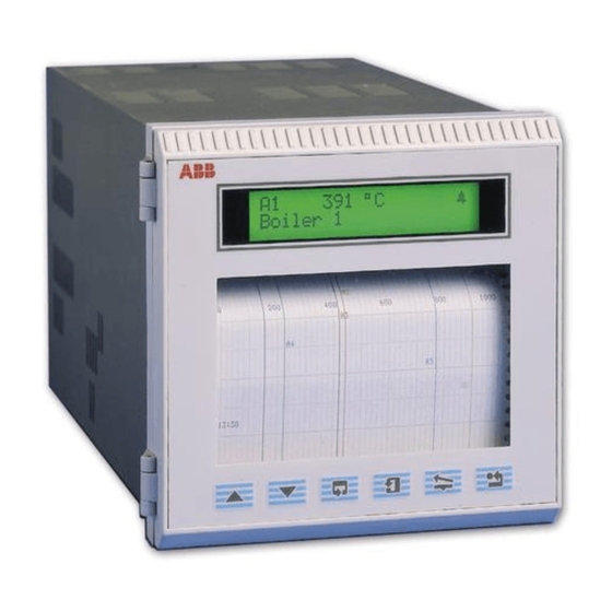
- Page 2 FRONT PANEL KEYS A1 225.8°C BOILER 1 TEMPERATURE Advance to Sideways Scroll next page Page 1 Page 2 Frame 1 Frame 1 Down Scroll Advance to next frame Frame 2 Frame 2 Raise and Lower Parameter V alue Adjust Flashing Enter Prompt Store Parameter X Select...
- Page 3 EDITING TEXT Select character using the keys. Flashing 6789:;<=?@ABCDEFG Flashing Enter character using the . key Select next character using the keys. Flashing JKLMNOPQRSTUVWXYZ Flashing Enter character using the . key Repeat until message complete.
- Page 4 St Neots, U.K. – Cert. No. Q5907 environmental applications. Stonehouse, U.K. – Cert. No. FM 21106 As a part of ABB, a world leader in process automation technology, we offer customers application expertise, service and support worldwide. EN 29001 (ISO 9001) We are committed to teamwork, high quality manufacturing, advanced technology and unrivalled service and support.
-
Page 5: Getting Started
GETTING STARTED The multipoint chart recorder provides accurate and reliable recording of 1, 2, 3 or 6 process signals on a 100mm wide chart. In-built text printing capabilities give clear annotation on the chart of time, date, scales and channel identifiers. A clear view of process status is provided by the liquid crystal display (l.c.d.) and up-to-the-minute recording can be quickly examined by means of the Easy View facility. -
Page 6: Table Of Contents
CONTENTS Section Page Section Page GETTING STARTED ............. 1 INSTALLATION ............31 Siting ..............31 CHARTS AND PENS ............ 3 Mounting ............31 Loading a Roll Chart .......... 3 Access to Terminals and Connections ..... 33 Loading a Fanfold Chart ........6 4.3.1 Removing the Chassis ....... -
Page 7: Charts And Pens
1 CHARTS AND PENS 1.1 Loading a Roll Chart – Fig. 1.1 The following procedures assume that the instrument has been installed in accordance with the instructions given in Section 4. Caution. • Channel values and text messages are not recorded during chart reloading and cannot be printed when the chart reload is complete. - Page 8 LOAD NEW ABB CHART Remove the old chart and load the new chart – see Fig. 1.2 (refer to Section 6, Spares List for part numbers). When a new chart is fitted and the cassette is replaced, press the key.
- Page 9 1 CHARTS AND PENS… …1.1 Loading a Roll Chart – Fig. 1.2 Insert spindle Caution. Ensure the correct chart type is set in the into roll – see Section 3.4.1. Chart Control Configuration Page Load roll into cassette Lift Catch Remove chart unit Wrap chart around cassette...
-
Page 10: Loading A Fanfold Chart
PRESS ENTER Load new fanfold chart – see Fig. 1.3 (refer to Section 6, Spares List for part LOAD NEW ABB CHART numbers). When a new chart is fitted and the cassette replaced, press the key. The chart moves forward approximately 30mm to take up any slack. - Page 11 CHARTS AND PENS… …1.2 Loading a Fanfold Chart – Fig. 1.3 Caution. Ensure the correct chart type is set in the – see Section 3.4.1. Chart Control Configuration Page Flip up guide Lift Catch Clip tension bar into catch Remove chart unit Feed chart under Rotate gear tension bar and guide...
-
Page 12: Fitting A Pen Capsule
…1 CHARTS AND PENS 1.3 Fitting a Pen Capsule – Fig. 1.4 Ensure that the power supply is on. Fit a new capsule as shown in Fig. 1.4. Refer to Section 6, Spares List for part numbers. Note. After fitting a new capsule, the ink flow takes a short time to achieve full color density. Display PEN LIFT ACTIVATED... -
Page 13: Chart Printout
CHARTS AND PENS 1.4 Chart Printout – Fig. 1.5 In addition to displaying up to six traces, the chart printout can contain text messages printed as events occur, such as process alarms, or at regular intervals, such as date/time and scale. End of Chart Warning –... -
Page 14: Operation
2 OPERATION 2.1 Introduction 2.1.1 Operator Level Pages – Fig. 2.1 An overview of the is contained on the back cover fold-out. Operator Level Pages ALARM SECURITY CHART OPERATING CONFIGURATION LEVEL (BASIC) PAGE PAGES ACCESS DISPLAYS Fig. 2.1 Operator Level Pages 2.1.2 Instrument Start-up –... -
Page 15: Operating Page
2 OPERATION… 2.2 Operating Page is the default start page. Operating Page Note. • Autoscroll is enabled automatically on power-up. To disable/enable autoscroll press the key. Pressing the keys at any point in the autoscroll cycle also sets autoscroll off. •... -
Page 16: Easy View (Roll Chart Only)
…2 OPERATION 2.2.1 Easy View (roll chart only) – Fig. 2.4 Easy View allows the operator to view the most recently printed area of the chart. The chart is wound forward for a short distance and returns automatically to its original position a few seconds later. Channel values and text messages are buffered during Easy View and are printed out when recording is resumed. -
Page 17: Alarm Acknowledge Page
OPERATION… 2.3 Alarm Acknowledge Page This page is displayed only when alarms are active and the is NORMAL or LATCH – see Section 3.3.2. Acknowledge Type There are two types of alarms: Process Alarms System Alarms Up to 12 alarms assignable to any Up to 6 input failure alarms activated by analog input and activated by pre- an input being outside its pre-defined... -
Page 18: Security Access
…2 OPERATION 2.4 Security Access – Fig. 2.5 A security system prevents tampering with the secure parameters and has two levels of access. Information. • Security Level 1 – access to Load Chart Page • Security Level 2 – access to the Configuration Level Pages If necessary, Security Access can be disabled to allow entry to all pages by setting the passwords to 0 –... -
Page 19: Configuration
3 CONFIGURATION 3.1 Introduction – Fig. 3.1 An overview of the Configuration level is contained on the back cover fold-out (outer). SECURITY ACCESS LOAD CHART CONFIGURATION PAGE PAGE LEVEL (BASIC) ANALOG INPUTS ALARMS ALARMS CHART OUTPUT MODULES OPERATOR SET-UP Fig. 3.1 Configuration Level Pages 3.1.1 Accessing the Configuration Level –... -
Page 20: Analog Inputs
…3 CONFIGURATION 3.2 Analog Inputs 3.2.1 Analog Input Configuration Page Information. • Up to 6 analog inputs – on standard boards (inputs A1 to A6). • Universal inputs – mV, mA, V, THC, RTD and resistance. • Internal cold junction compensation. •... - Page 21 3 CONFIGURATION… …3.2.1 Analog Input Configuration Page ANALOG INPUT CONFIGURATION Input to Configure INPUT TO CONFIGURE Select the analog input to configure (A1 to A6). On entry the default is NONE. None Input Type ANALOG I/P Select the analog input type required: INPUT TYPE –...
- Page 22 …3 CONFIGURATION …3.2.1 Analog Input Configuration Page Input Engineering Range ENGINEERING For inputs with RTD and thermocouple linearizers RANGE FS Defines both the display range of the instrument and the operating range of the input linearizer. The limits are as specified in table 3.2, according to linearizer type.
-
Page 23: Input Conditioning Configuration Page
3 CONFIGURATION… 3.2.2 Input Conditioning Configuration Page Information. • Mains filter – selectable for maximum noise rejection. • Quick input configuration feature (copies channel A1 settings to all other inputs) – for applications where all the inputs are the same. INPUT CONDITIONING CONFIGURATION Rejection Frequency... -
Page 24: Scale Adjustment Page
…3 CONFIGURATION 3.2.3 Scale Adjustment Page Information. • Analog inputs – do not require re-calibrating when the input or range is changed. • Scale Adjustment Reset – removes any previously programmed offset or scale adjustment settings. • System Offset Errors – can be removed using Offset Adjustment. •... - Page 25 3 CONFIGURATION… …3.2.3 Scale Adjustment Page SCALE ADJUSTMENT Input to Adjust INPUT TO ADJUST Select the analog input to adjust (A1 to A6). On entry the default is NONE. NONE Scale Adjustment Reset RESET SCALE ADJUST Select YES to reset the analog input offset and span values to their nominal values.
-
Page 26: Alarms
…3 CONFIGURATION 3.3 Alarms 3.3.1 Process Alarm Configuration Page Information. • 12 Process alarms – identified A to M (excluding I). • Up to six alarms can be assigned to relays. • High/low process alarms. • Alarms assignable to any analog input. •... -
Page 27: Alarm Acknowledge Configuration Page
3 CONFIGURATION… 3.3.2 Alarm Acknowledge Configuration Page Information. • Three operator acknowledge options. • Global alarm acknowledgment – from internal or external digital source. • Indication of power failure – can be enabled/disabled. ALARM ACKNOWLEDGE PAGE Acknowledge Type ACKNOWLEDGE TYPE Select the type of alarm acknowledge facility required: LATCH LATCH... -
Page 28: Chart
…3 CONFIGURATION 3.4 Chart 3.4.1 Chart Control Configuration Page Information. • Set up to 3 independent chart speeds – selectable from operating level or by digital signal. • Enable/disable printing of text (except alarms). • NO AUTO PRINT facility – allows an unbroken trace at higher chart speeds (> 120mm/h), with printing of time, scales, etc. - Page 29 3 CONFIGURATION… …3.4.1 Chart Control Configuration Page Text Print Enable TEXT PRINT Select the text printing required: NO AUTO PRINT NO AUTO PRINT – disable printing text that printed automatically, i.e. Time, Date, Channel Tags and Trace Identifiers – enable printing of all text except alarm messages –...
- Page 30 …3 CONFIGURATION …3.4.1 Chart Control Configuration Page Set Paper Length SET PAPER LENGTH Set the required paper length in 1m increments. For roll chart, the maximum paper length is 25m. For fanfold chart, the maximum paper length is 12m. Fanfold Chart Roll Chart Automatic Chart Rewind AUTOMATIC REWIND AT...
-
Page 31: Chart Scaling Configuration Page
3 CONFIGURATION… 3.4.2 Chart Scaling Configuration Page Information. • Up to six independent scales can be printed, with selectable interval between scales. • Programmable full scale and zero values. • Test print facility to enable instant checking of entered scale. CHART SCALING CONFIGURATION Scale to Configure... -
Page 32: Pen Position Configuration Page
…3 CONFIGURATION 3.4.3 Pen Position Configuration Page Information. • Allows accurate calibration of the pen positions on the chart. • Can be used to remove effects of inconsistencies in the charts. PEN POSITION CONFIGURATION Pen Calibration Enable PEN CAL ENABLE Select YES to advance to the zero and full scale setting parameters. -
Page 33: Output Modules
3 CONFIGURATION… 3.5 Output Modules Information. • Output modules can be fitted into module positions B and C. • Automatic detection of type of modules fitted. • Programmable sources for relay outputs. • Programmable polarity for each relay output. 3.5.1 Output Module Configuration Page – Relay Modules Select Relay Output Digital Source Polarity Selection... -
Page 34: Operator Setup
…3 CONFIGURATION 3.6 Operator Setup 3.6.1 Security Access Configuration Page Information. • The 2 levels of security are: – access to Level 1 Load Chart Page – allows access to and the Level 2 Level 1 Configuration Level. • This page is used to set the passwords for the security levels. SECURITY ACCESS CONFIGURATION Set Access Level 1 Password... -
Page 35: Installation
4 INSTALLATION EC Directive 89/336/EEC 50°C In order to meet the requirements of the EC Directive 89/ Max. 336/EEC for EMC regulations, this product must not be used in a non-industrial environment. 0°C Min. End of Life Disposal A – Within Temperature Limits This instrument does not contain any substance that will cause undue harm to the environment. - Page 36 …4 INSTALLATION …4.2 Mounting – Figs. 4.3 and 4.4 Caution. The clamp Cut a hole in the panel (see Fig.4.3 for dimensions) must fit flat on the instrument casing. If the clamp is bowed, the securing screw is overtight and sealing problems may 30°...
-
Page 37: Access To Terminals And Connections
4 INSTALLATION… 4.3.1 Removing the Chassis – Fig 4.6 Warning. Before making any connections, The chassis must be removed to gain access to the electrical ensure that the power supply, any high voltage-operated connections and/or analog input modules. control circuits and high common mode voltages are switched off. -
Page 38: Electrical Connections
…4 INSTALLATION 4.4 Electrical Connections – Fig. 4.7 The terminals accept cables up to 2.5mm cross section. Note. For the combination of this apparatus with other apparatus and/or for its connection to installations, the following notes apply: • Always route signal leads and power cables separately, preferably in earthed metal conduit. •... -
Page 39: Analog Input Connections
4 INSTALLATION… 4.5 Analog Input Connections White White – – – – – 3rd Ld 3rd Ld Sleeved Link Each lead must be of equal resistance and less than 50Ω Diode supplied in accessory pack. A – Voltage B – Current C –... -
Page 40: Transmitter Power Supply
…4 INSTALLATION 4.5.4 Transmitter Power Supply – Fig. 4.9 Information. The power supply board provides a transmitter power supply capable of powering three loops. 2-wire Transmitter Power Supply (24V d.c., 70mA max.) – Analog I/P – – Fig 4.9 Transmitter Power Supply 4.5.5 Relay Outputs –... -
Page 41: Selecting Analog Input Types
4 INSTALLATION 4.5.6 Selecting Analog Input Types – Fig. 4.11 The analog inputs must be set up for the input type required. Caution. Static electricity can seriously damage components. Wear an earth strap and/or use an anti-static bench when dismantling the instrument. Remove tie-bar Analog Input PCB (TB1) Set the input link positions... -
Page 42: Simple Fault Finding
5 SIMPLE FAULT FINDING If the instrument does not appear to be working satisfactorily carry out the following checks before contacting the Customer Support Organization. • Are all the connections made correctly? • Is there power to the instrument? • Is there a signal at the input terminals? •... -
Page 43: Arc Suppression Capacitors
6 SPARES LIST …5 SIMPLE FAULT FINDING 5.1 Arc Suppression Capacitors – Fig. 5.1 6.1 Consumables Arc suppression capacitors are fitted across the contacts of The following spares are required at regular intervals: the alarm/control relays. If these contacts are used to operate Item Part No. -
Page 44: Index
INDEX …C Alarms Configuration Operating Page Acknowledging ....13, 23 Alarms. See Alarms: Configuring Autoscroll ......10, 11 Configuring ....... 22 Analog Inputs ......16 Chart Loading. See Chart: Hysteresis ......... 22 Chart ......... 24 Loading Message Printing ...... 25 Input Conditioning ..... - Page 45 PRODUCTS & CUSTOMER SUPPORT A Comprehensive Instrumentation Range Customer Support Analytical Instrumentation ABB Instrumentation provides a comprehensive after sales service via a Worldwide Service Organization. Contact one of • Transmitters the following offices for details on your nearest Service and...
-
Page 46: Operator Level Overview
OPERATOR LEVEL OVERVIEW (Section 2.3) (Section 2.4) (Section 3.1) (Section 2.1) (Section 1.1 & 1.2) OPERATING ALARM SECURITY CHART CONFIGURATION PAGE DISPLAYS PAGES ACCESS LEVEL No Alarms OPERATING DISPLAYS A1 225.8°C BOILER 1 TEMPERATURE • Channel reading, tag & units •... - Page 47 CONFIGURATION LEVELS OVERVIEW BASIC LEVEL (Section 3.2.1) (Section 3.2.2) (Section 3.2.3) Exit ANALOG INPUT INPUT CONDITIONING SCALE Analog inputs CONFIGURATION ADJUSTMENT CONFIGURATION Alarms • Configure input(s) • Set mains rejection • Reset scale adjust Chart frequency • Adjust offset O/P Modules •...
- Page 48 The Company’s policy is one of continuous product improvement and the right is reserved to modify the information contained herein without notice. © ABB 2000 Printed in UK (05.00) ABB Instrumentation Ltd. ABB Automation Inc. ABB Instrumentation SpA St. Neots...
Need help?
Do you have a question about the SR100B and is the answer not in the manual?
Questions and answers