Table of Contents
Advertisement
Product Manual
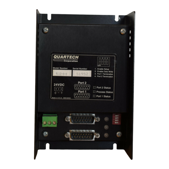
Model 9112
Communication Bridge
Data Control Projects
Quartech Corporation
15923 Angelo Drive
Macomb Township, Michigan 48042-4050
Phone: (586) 781-0373 FAX: (586) 781-0378
www.QuartechCorp.com
PM9112C Revision 1
The product described in this document can have a variety of uses, the user and those responsible for applying this
equipment must satisfy themselves as to the acceptability of each application and the use of the unit. Under no
circumstances will QUARTECH CORPORATION be responsible or liable for any damage, including indirect or
consequential losses resulting from the use, misuse, or application of the unit.
The text, illustrations, charts, and examples included in this document are intended solely to help explain applications
of the product. Due to the many variables associated with specific uses or applications, QUARTECH CORPORATION
cannot assume responsibility or liability for actual use based upon the data provided in this document.
No patent liability is assumed by QUARTECH CORPORATION with respect to the use of circuits, information,
equipment, or software described in this document.
This document is subject to change without notice.
PM9112C Revision 1
Advertisement
Table of Contents

Subscribe to Our Youtube Channel
Related Manuals for Quartech 9112


Summary of Contents for Quartech 9112
- Page 1 The text, illustrations, charts, and examples included in this document are intended solely to help explain applications of the product. Due to the many variables associated with specific uses or applications, QUARTECH CORPORATION cannot assume responsibility or liability for actual use based upon the data provided in this document.
-
Page 2: Table Of Contents
Function Block Editor ......9 Section 3: Download 9112 Configuration ..... 11 Section 4: Download Project File . -
Page 3: Section 1: Introduction
The internal architecture of the 9112, as an option, provides both retentive and non-retentive memory areas that can be used for data storage. The project designer allocates internal memory by creating a database. A database associates a data resource to an assigned label name. -
Page 4: New Project Creation
The 9112 is shipped from the factory with manufacturing test code installed. The first step in commissioning the 9112 is to create a project. To create a new project it is necessary to select the communication drivers that will be installed to the various ports within the 9112. -
Page 5: Section 2: Edit Project
Project Folder A project is a collection of files within a file folder or directory. The file folder or directory name is the project name. The project files are automatically created and maintained by ProjectMaker 9112. Configuration: (Port1 & Port2) These files represent the physical communication ports on the Model 9112. -
Page 6: Drivers Database
Drivers Database The driver firmware loaded into the 9112 allows it to communicate with a specific device through a communication port. The parameters available within a specific device vary along with the reference designations used to access them. -
Page 7: Non-Retentive Ram Database
Typically a numeric value will use four bytes of data while a string may require the fill 128 bytes. When the 9112 is first powered the number of bytes allocated to an element is zero and remains at zero until a value or string is stored. -
Page 8: System Database
Retentive RAM Files The Retentive RAM File allow initial values or strings to be placed into the 9112 Retentive RAM memory during project download. Before data can be specified within the file the Retentive RAM database must be created by assigning label names to the desired File/Element numbers. -
Page 9: Logic Block Editor
Page 7 Section 2: Edit Project Above is a typical Retentive RAM File Editor. The database labels that appear here are the labels that were assigned within the Retentive RAM Database Editor and can not be changed in this list. The values entered can be signed or unsigned long integers, single precision floating point, or ASCII text string up to 128 characters. -
Page 10: Processing Logic Blocks
Page 8 Section 2: Edit Project The instructions for an application are defined within logic blocks that are created and edited within the logic block editor. A logic block is an eight by eight matrix that allows logic elements to be placed using drag and drop. Each element within a logic block has an associated parameter file that is accessed by double clicking the element. -
Page 11: Function Block Editor
Page 9 Section 2: Edit Project Function Block Editor The function block editor allows the entry and editing of all the parameters necessary to specify the operation a function block will perform. The fields and options available will vary depending on the specific function block. The function block editor is opened by double-clicking on a function block or right-clicking then choosing edit from the pop-up menu. - Page 12 Page 10 Section 2: Edit Project Function Block specific help is available from within ProjectMaker 9112. From the Menu Bar choose Help > Describe or press hot key F3, then left-click on the block icon. Many of the function blocks have a Count field that allows multiple iterations of the function to execute. When combined with incremental Source and/or Destination fields multiple variables can be modified within this single scan.
-
Page 13: Section 3: Download 9112 Configuration
Download Drivers button will become active. 4: Download the drivers to the 9112 If the Clock/Calendar option is installed, then it may also be read or written. When the driver download is complete, remove power from the 9112 and set DIP switch one to the off position. A project file may now be downloaded. -
Page 14: Section 4: Download Project File
º Download to 9112 4. Go Online to establish a connection with the 9112 and read its current configuration. This will establish a connection between the computer and 9112 and verify a compatible driver group is installed. If a successful connection is established then the Download Project button will become active. -
Page 15: Section 5: Status Indicators
Page 13 Section 5: Status Indicators Three Light Emitting Diodes (LED) are visible through the front cover of the 9112 and provide operational status. The status displays can be categorized into four groups. Power-up Cycle The following displays could occur during initial powering of the device. -
Page 16: Appendix A: Electrical / Mechanical Information
Refer to section 5 for information on specific status conditions. All dimensions in inches Auxiliary Port: Some models of the 9112 provide additional connections, switches, and indicators. An addendum sheet is available that describes the specific function and operation of these devices. Specifications: Electrical: 24 VDC, ±5%, @ 200 ma... - Page 17 Electrical / Mechanical Information The 9112 is designed to be mounted to a panel within an enclosure. Care must be taken to prevent metal chips or other conductive particles such as wire clippings from entering the unit during installation. Failure to protect the unit may cause damage when power is applied and may void the warranty.
- Page 18 ProjectMaker 9112 software is available free of charge at the Quartech Corporation web site. Also available is the latest version of this product manual plus other related manuals and documents. Quartech Corporation 15943 Angelo Drive Macomb Township, Michigan 48042-4050 Phone: (586) 781-0373 FAX: (586) 781-0378 Email: Sales@QuartechCorp.com www.QuartechCorp.com...
Need help?
Do you have a question about the 9112 and is the answer not in the manual?
Questions and answers