DINA SafeLine DNSL-ZM Product Information
Hide thumbs
Also See for SafeLine DNSL-ZM:
- Original instruction manual (28 pages) ,
- Original instruction manual (28 pages)
Table of Contents
Advertisement
Advertisement
Table of Contents

Subscribe to Our Youtube Channel
Related Manuals for DINA SafeLine DNSL-ZM


Summary of Contents for DINA SafeLine DNSL-ZM
- Page 1 Safety for men and machines SafeLine Product information...
- Page 2 DlNA Elektronik GmbH Esslinger Straße 84, 72649 Wolfschlugen Tel. 07022/95 17-0, Fax 07022/95 17-51 www.dinaelektronik.de, info@dinaelektronik.de Quality management system DQS certificated according to DIN EN ISO 9001: 2000 Reg.-Nr.67542-01...
- Page 3 SafeLine modules Central module DNSL-ZM 6 safe digital inputs 4 safe positive switching outputs The direct path to safe automation 2 positive switching outputs, free configurable 1 positive switching output, system ready V24 interface Central module DNSL-ZMB 16 safe digital inputs 2 safe positive switching outputs 1 relay output with 2 safe contacts 1 positive switching output, system ready...
-
Page 4: Table Of Contents
Product information Contents Page Safety regulations Intended usage SafeLine: Product description SafeLine DESIGNER DNSL-ZM: Central module DNSL-ZM input usage Outputs usage Special functions RTDS Pulse generator via IF1 DNCO Function: Parameter mask Position monitoring of axis with DNSL-DS DNSL-ZMB, DNSL-ZMT: Central modules Inputs usage DNSL-ZMB, DNSL-ZMT: Standstill and motion monitoring DNSL-ZMB, DNSL-ZMT: Output usage... -
Page 5: Safety Regulations
Product information Safety regulations The unit may only be installed and operated by those who are qualified electrical engineers or have received sufficient • training and are familiar with both these instructions and the current regulations for safety at work and accident prevention. Follow VDE, EN as well as local regulations especially as regards preventative measures! Ignoring the safety regulations can lead to death, serious injury or cause considerable damage! •... -
Page 6: Safeline: Product Description
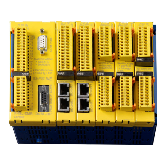
Product information SafeLine: Product description SafeLine is housed in a metal rack type enclosure. It can be mounted by spring fasteners to a DIN rail. The individ- ual functional modules are pluggable. The equipment is available in different housing sizes, depending on the number of functional modules to be used. -
Page 7: Safeline Designer
Product information SafeLine DESIGNER 1. layer: Module layer Free circuit Selection Menu used modules Layer 2 (parameter mask) will be displayed by right click with mouse on the individual net list module. Position of modules motion control parameter Module selection The central module will always be put at slot ZM. - Page 8 Product information 2. layer: Parameter mask Selection timer(TC) Central module parameter mask Inputs, terminal: labelling of inputs I1 to I20 SK1 I1..I3, SK2 I4..I6, Restart: SK -Restart „manually“ by activating Q or „Auto.“ automatically SLOK SK1, SLOK SK2: the function SLOK SK1 and SLOK SK2 is only important, if: 1.
- Page 9 Product information Central module: selection A. relay, LM or Analogue Selection A. Relay, Contactor relay Selection (LM), logic modules Selection Analogue only with ZMT/ZMA Vref: Reference volt- age 15V, produced in SafeLine. Fields for labelling Fields to enter the Fields for voltage value labelling Trigger points at ZMT,...
-
Page 10: Dnsl-Zm: Central Module
Programming of the SafeLine unit is accomplished with the SafeLine Designer program on a PC. The completed program is transferred via the COM interface to the Safeline unit. The SafeLine DESIGNER is special software developed by DINA Elektronik. The operation voltage (24V DC) is supplied to the clamps A1 und A2. -
Page 11: Outputs Usage
Product information Outputs usage Wiring layer 1. Output O1 function may be defined in the parameter layer to one of the following: SLOK: Output indicating System Ready Semi conductor switch 2. FrqIn: possible only with DNSL-ZMB, ZMT and ZMR 3. O2, O3, O4 and O5 are redundant outputs made of a positive switching semi- conductor and a relay contact. -
Page 12: Dnco Function: Parameter Mask
Product information Parameter mask DNCO Parameter mask : Mask save and close. Selecting DNCO mask is available in every central module mask. Description of the parameter mask: See page 8 and 9. DNCO function: Parameter mask Two frequency tables containing up to 48 values each. Example: These values define the maximum monitored speeds. - Page 13 Product information Central modules DNSL-ZMB, DNSL-ZMT DNSL-ZMT Schematic DNSL-ZMB-DP Eingänge / Inputs Ausgänge / Outputs UB = 24V DC I19 I18 I17 I16 I15 I14 I13 I12 I11 I6 24V DC Netzteil Power supply COM PORT 24V intern DNSL-ZMB and ZMT can be ordered with an integrated field bus, Profibus or Ether cat module.
-
Page 14: Dnsl-Zmb, Dnsl-Zmt: Standstill And Motion Monitoring
As impulse device a proximity switch may be used. Setting the value for the motion control will be done using the PROFIBUS. The proceeding of programming is received by DINA Elektronik. ν ν ν ν ν ν ν ν... - Page 15 Unused clamps I16-I20 may be left unconnected. resistor values, contact Note: Digital inputs and analogue safety mat inputs will be DINA Elektronik. processed in two channel mode and tested for plausibility on the Central – and all Function modules. There is no single channel processing.
-
Page 16: Memory Of Application
Product information Parameter mask DNSL-ZMT Reset of safety mat The reset of the virtual con- tacts of the mat can be automatically (AUTO). Safety The contacts close again, if Shutdown mat the mat is inactivated. low value If (MAN) is selected, the re- Safety set has to be activated via Shutdown mat... -
Page 17: Description Of The Wiring Layer
As impulse device a proximity switch may be used. Setting the value for the motion control will be done using the Profibus. The proceeding of programming is received by DINA Elektronik. ν ν ν ν... -
Page 18: Memory Of Application
Product information Parameter mask: Descrition: Look at page 8 and 9 Memory of application All application information will be stored on a pluggable „Memory card“ Type DNSL-MC. This card is plugged in- ternally on the central module and is part of the central module DNSL-ZMB, ZMT and ZMR. It can also be ordered separately. -
Page 19: Description Of Wiring Layer
Product information DNSL-KM Relay module Connection scheme DNSL-KM Ausgangskontakte / Ouput contacts 54 63 64 73 74 83 84 K1 13 14 23 24 33 34 43 44 Power Info 24VDC intern / internal Output expansion for DNSL-ZMR with DNSL-KM: The central module DNSL-ZMR can control directly a relay module of type DNSL-KM. - Page 20 Product information DNSL-ZMK Central module Connection scheme Wiring layer Eingänge / Inputs Ausgänge / Outputs UB = 24V DC 24V DC Netzteil Power supply COM PORT 24V intern Inputs usage Look at DNSL-ZM page 10 Outputs usage Look at DNSL-ZMB page 14 Special functions Look at DNSL-ZMB page 14 Parameter mask...
-
Page 21: Outputs Usage Parameter Mask
Product information DNSL-ZMA: Central module Wiring layer Connection scheme Eingänge / Inputs Ausgänge / Outputs UB = 24V DC 0V U Uref analog 24V DC Netzteil Power supply COM PORT 24V intern Inputs usage Look at DNSL-ZM page 10 Outputs usage Look at DNSL-ZMB page 14. - Page 22 Product information Central modules: Software elements Times: it can be selected 12 off- and 3 on-delayed or 9 off- and 6 on-delayed Timer off-delayed Timer on-delayed diagram off delayed Timing diagram on delayed +24V virtual +24V virtual 13 / 14 - 63 / 64 13 / 14 - 63 / 64 71 / 72 - 81 / 82 71 / 72 - 81 / 82...
- Page 23 Pin is needed if a password is inserted the 1st. time in SafeLine or if the password is no more available. In this case the PIN-Number must be inserted. The PIN number is only known by DINA and the responsible customer stuff member.
-
Page 24: Safeline Diagnostic
Product information SafeLine diagnostic Diagnostic of internal wiring Diagnostic This diagnostic is only possi- ble with a connection be- tween PC and SafeLine via the COM PORT interface. Activated by pushbutton. Active virtual connections are shown in RED, inactive con- nections are shown in BLUE. - Page 25 Product information DNSL-DS and DNSL-DR: Standstill, motion and direction monitoring DNSL-DS for encoder: connection scheme Potential Ausgänge/ Outputs Eingänge / Inputs Eingänge / Inputs DNSL-DS P1 P2 O1 O2 O3 O4 B11 B12 B13 B14 B21 B22 B23 B24 Encoder 1 Encoder 2 Info Power...
- Page 26 Product information DNSL-DS and DNSL-DR: Function of standstill, motion and direction monitoring For monitoring normally the feedback system of the drive is used. Direction of motion monitoring Wiring Layer 1. Monitoring The virtual contact LR1 (LR2) for direction monitoring is closed if drive is in standstill condition (SS1 (SS2) closed) or rotation is clockwise (left to right).
-
Page 27: Usage Of Dnco Function
Product information DNSL-DS, DNSL-DR: DNCO function SH-K SH-K DNCO1 DNCO1 DNCO1 Steuer- Steuer- DNSL-ZM elektronik elektronik DNSL-DS Control Control device device The DNCO function is provided to adjust the monitored speed of a machine in automatic operation to the current process needs. -
Page 28: Mask Of Parameter
Product information Usage of the outputs Four semiconductor outputs are available on the motion monitoring module. The supply for outputs O1 and O3 is clamp P1, clamp P2 is the supply for O2 and O4. The outputs may be configured using the parameter layer to the following: Clock output supply for cross-circuiting detection in safety circuits, No virtual wiring possible... - Page 29 Product information DNSL-IN: Input module DNSL-IN Connection scheme Ausgänge Ausgänge Eingänge / Inputs Eingänge / Inputs Outputs Outputs O11 O12 I11 I12 I13 I14 I15 I16 I17 I18 O21 O22 I21 I22 I23 I24 I25 I26 I27 I28 Info Power Info 24V Intern 24V Intern...
-
Page 30: Parameter Mask
Product information Output usage DNSL-IN O11, O12 and O21, O22 are positive switching semiconductors outputs. The Wiring layer 24V supply for these 0utputs is from clamp A1 on the central module. O11, O12 and O21, O22 may be configured using the parameter mask to the following: Clock output supply for cross-circuiting detection in safety circuits, No virtual wiring possible... - Page 31 Product information DNSL-IO: Input/ output module Connection scheme Potential Ausgänge / Outputs Eingänge / Inputs P1 P2 O11 O12 O13 O14 O15 O16 O17 O18 O21 O22 I21 I22 I23 I24 I25 I26 I27 I28 Info Power Info 24V Intern Inputs usage Safety circuit 1 (SK1) Emergency Stop...
- Page 32 Product information Outputs usage Wiring layer DNSL-IO: O11 to O22 are positive switching semiconductors outputs. The 24V supply for these outputs is from: O11, O13, O15 and O17 via terminal P1 O12, O14, O16 and O18 via terminal P2 O21 and O22 by terminal A1 on the central module. O11 to O22 may be configured using the parameter mask to the following: Setting of O11 to O18 Paired output...
-
Page 33: Parameter Mask
Product information Parameter mask Name 1, 2: Fields to label the outputs and inputs block O11-O18, O21, O22: Fields to label the outputs I11-I18: Fields to label the inputs P1, P2: Fields to label the supply terminals of the outputs O11-O18 SK1, SK2 Restart: SK -Restart „manually“... - Page 34 Product information DNSL-RM, DNSL-RM 230: Relay modules DNSL-RM DNSL-RM: Connection scheme DNSL-RM-230 Ausgangskontakte / Ouput contacts 53 54 63 64 73 74 83 84 81 11 12 13 14 23 24 33 34 43 44 Power Info DNSL-RM-230: Connection scheme Ausgangskontakte / Ouput contacts 53 54 63 64 73 74 83 84 13 14 23 24 33 34 43 44...
-
Page 35: Spindle Activation And Deactivation
Every spindle must have assigned an ID-number saved in the PLC. Up to 14 spindles are possible. This function is possible with the DINA control equipment DNCO1 for selecting and display the wished spindle. The 3. cipher of the ID-number is the position of the monitoring module in the rack of SafeLine. The 4. cipher is 1 for the first monitoring at the module and 2 for the second monitoring at the module. - Page 36 Product information The table below shows the ID Numbers of 14 spindles: Position in the DNCO table Spindle ID-number hexadecimal slot at rack Motion monitoring 0x21 0x22 0x31 0x32 0x41 0x42 0x51 0x52 0x61 0x62 0x71 0x72 0x81 0x82 0xF3 alle alle Spindle deactivation...
-
Page 37: Field Bus Communication
Product information Field bus: Output data Eight bytes are defined as output-data. Only 3 of the 8 bytes are visible in the DESIGNER (AB1 to AB3). All other bytes are used for special purposes. The individual data bits will be assigned in the wiring layer of the DESIGNER. Field bus: Virtual wiring of output data from field bus Master Left click on the symbol will activate the wiring layer. -
Page 38: Dnsl-Zmr
Product information Dimension diagram and assembling width / length width / length high Breite / width Breite / width 58mm 58mm The smallest width is 58mm. 15mm ELEKTRONIK GmbH ELEKTRONIK GmbH The widths are depended from the central module type and the number of the function modules. - Page 39 Product information echnical data General t Electrical characteristics Operation voltage U 24V DC on A1/ A2 central module for complete unit 85 - 110% Margins U Ripple U Max. 10 % Power consumption at U Number of Module dependent Environment conditions Operation temperature -10 to +60°C according DIN IEC 60068-2-3 -40 to +85°C according DIN IEC 60068-2-3...
- Page 40 Product information Technical data DNSL-ZMB, DNSL-ZMT DNSL-ZMA, DNSL-ZMK Power consumption at A1, A2 Max 2,9W Internal fuse 6A, automatic reset Maximum frequency for I11 – I14 and O1 as input (FrqIn) 1200Hz with DNSL-ZMB, ZMT Switch and continuous current output O1, resistive load Max.
- Page 41 Product information DNSL-DS, DNSL-DR technical data DNSL-DS, DNSL-DR technical data Power consumption at A1, A2 via the central module Max 2,5W Supply voltage at P1, P2 24V DC +10% -15% Ripple at P1, P2 Input signal level encoder, Sin/ Cos 0,8-1Vss Input signal level encoder, TTL 4-5V...
- Page 42 Product information DNSL-RM technical data Power consumption at at A1, A2 via the central module Max 4,8W Minimum current of contacts 11/12 to 83/84 10mA Maximum current of contacts 11/12 and 81/82 DC13: 1A, 24V Technical data of output contacts 13/14 to 83/84 according DIN EN 60947-4-1/ EN 60947-5-1 Switching capacity DC13: 4A, 24V 0,1Hz...
- Page 43 Product information Products: safety technology SafeLine redaction 11 date 10.04.09 page 43 from 48...
- Page 44 Product information Error massage DESIGNER Program start Error: An older slw file was Error: File (sld opened with a new version of help.chm) is not Designer. existing. Solution: The old slw file has to Solution: Install all be converted in a new data format. SafeLine software Error at projecting of the rack Error: Field bus not at the first...
- Page 45 Product information Error motion monitoring module Error: The frequency value is to high. Solution: The maximal fre- quency value is 499000 Hz. Handling errors Problem: Online diagnostic Problem: No print option is without a downloaded project selected. Solution: Please download a Solution: Please select a print project from PC or SafeLine.
- Page 46 Product information Certificate Products: safety technology SafeLine redaction 11 date 10.04.09 page 46 from 48...
- Page 47 Product information Products: safety technology SafeLine redaction 11 date 10.04.09 page 47 from 48...
Need help?
Do you have a question about the SafeLine DNSL-ZM and is the answer not in the manual?
Questions and answers