Table of Contents
Advertisement
Quick Links
Advertisement
Table of Contents

Related Manuals for GKD 2 Series


Summary of Contents for GKD 2 Series
- Page 1 2RCI User Manual M2000001 v1.4...
-
Page 2: Change History
Document created. Update from the NPN V5 version V1.1 26/11/2014 Add Slew and I/O module options V1.2 04/07/2016 General update and reformat of entire document V1.3 16/08/2017 Added new Virtual wall functionality V1.4 20/11/2017 Update to new branding and part numbers M2000001 GKD Technik Ltd... -
Page 3: Table Of Contents
Mode Menu Setting a Height Limit Cancelling a Height Limit Setting a Slew Limit Virtual Walls Dig Mode Depth Setting Automatic Slew Based Lifting Duties Full Motion Cut on Overload Test Function System Layout Component Location M2000001 GKD Technik Ltd... -
Page 4: Introduction
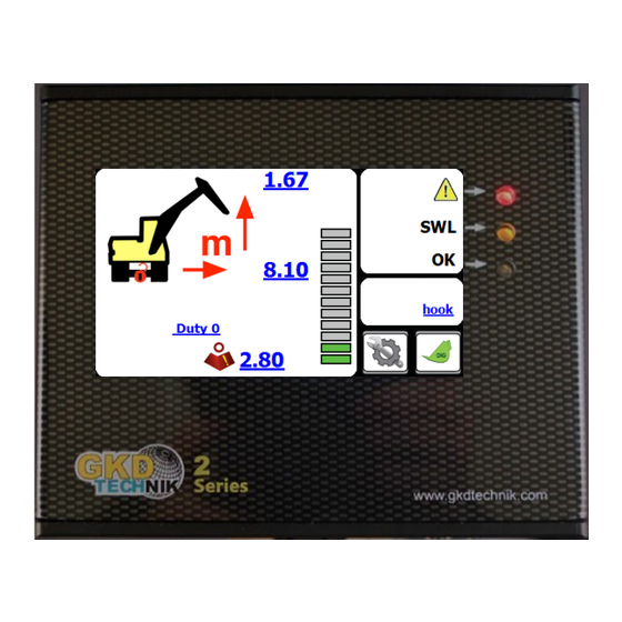
Bucket Pin Height Overload LED (or system fault) Approach LED Power LED Axle Lock (System OK) Indicator Duty Indicator Current Lifting Point Dig Mode Button Load on Hook Rated Capacity Bucket Pin Radius Mode Button Lift Status Bar M2000001 GKD Technik Ltd... -
Page 5: Lifting Operation
Selection of the lifting mode is made from the MODE screen. Access to this screen is by pressing the MODE button on the front screen. There are three available lift configurations. The mode is selected by repeatedly pressing the coloured lift duty button. M2000001 GKD Technik Ltd... -
Page 6: Lifting Mode
The front screen will show a ‘JIB’ status. In addition there is a warning if the hydraulic pressure is exceeded in the jib cylinder. M2000001 GKD Technik Ltd... -
Page 7: Mode Menu
Pressing “NO” will allow the height to be set by moving the machine to the maximum height. Press “YES” when the machine is in the correct position. NOTE this screen will timeout if not selected within 10 seconds. M2000001 GKD Technik Ltd... -
Page 8: Cancelling A Height Limit
Then slew the machine right to the required position and press the “Set Right Limit” button. Return to the operator screen and check that the limits are working correctly by slewing the machine left and right until the limits are reached. M2000001 GKD Technik Ltd... -
Page 9: Virtual Walls
The system will then connect these points with a ‘virtual wall’ This is entered as a distance, in metres, from the which will then become the limit. centre of the machine. M2000001 GKD Technik Ltd... - Page 10 As the machine slews, its position and distance to the wall will be updated automatically. When the machine reaches the virtual wall, all relevant machine motions will be prevented from breaching the wall. This includes Boom and Dipper motions. M2000001 GKD Technik Ltd...
- Page 11 As the machine slews, its position and distance to the wall will be updated automatically. When the machine reaches the virtual wall, all relevant machine motions will be prevented from breaching the wall. This includes Boom and Dipper motions. M2000001 GKD Technik Ltd...
-
Page 12: Dig Mode
Alarm silenced icon Bucket Pin Radius Current Dig Depth Return to Lift Mode Target Level Indicator or Target Level To exit Dig Mode and return to Lifting Mode, press on the “Return to Lift Mode” button, shown above. M2000001 GKD Technik Ltd... -
Page 13: Depth Setting
Whenever the machine is moved it is recommended that the depth is reset by placing the bucket on the level previously dug and reset the depth by pressing dig mode, “NO” and “YES” to make the new bucket position to datum. M2000001 GKD Technik Ltd... -
Page 14: Automatic Slew Based Lifting Duties
Thus, more lift capacity can be attained for the machine over the front and rear than over the side, and the machine’s lift capability is maximised for the slew position of the machine. M2000001 GKD Technik Ltd... -
Page 15: Full Motion Cut On Overload
The test button sequence should be carried out regularly to verify the correct operation of warning devices. To access the “TEST” button, first press the “MENU” button. Then you can press on the “TEST” button. M2000001 GKD Technik Ltd... -
Page 16: System Layout
System Layout Component Location Typical locations of 2RCI components as installed onto a machine are shown here. M2000001 GKD Technik Ltd... - Page 17 Below is a link to the GKD Knowledge base where you can find definitions of all the error codes for the 2RCI System.
Need help?
Do you have a question about the 2 Series and is the answer not in the manual?
Questions and answers