Advertisement
Hardware Installation Manual
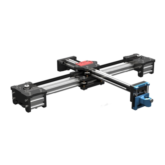
Support:VG-X4
Overall Size:570×436×88(L×W×H)
Print Size:310×256mm(L×W)
Powered by VigoTec 2019.
1.Parts list
Serial N
F1
F2
F3
P1
P2
P3
P4
P5L、P5R
P6
P7
P8
P9
W1
M1
M2
W2
S1
S2
S3
N1
N2
N3
Catalogue: 1. Parts list, 2. Installation, 3. Notice
1.1 list of VG-X4 Writing Machine Kits
430mm Aluminum profile
360mm Aluminum profile
Acrylic central plate A(Top,Thickness 8mm)
Acrylic central plate B(Middle,Thickness 8mm)
Acrylic central plate C(Bottom,Thickness 8mm)
Acrylic motor plate(Thickness 8mm)
Acrylic leg A(Inside,Thickness 8mm)
Acrylic leg B(Outside,Thickness 5mm)
Acrylic rear plate A(Thickness 8mm)
Acrylic rear plate B(Thickness 5mm)
Acrylic front plate(Thickness 8mm)
Synchronous pulley and Set screw
Inner hexagon screw(M5×45,Fastening the acrylic central plate and
Inner hexagon screw(M5×20,Fastening the acrylic leg plate, front
plate, rear plate and pen control kit/Laser kit)
Inner hexagon screw(M5×12,Fastening the acrylic motor, leg and
Antiskid nut(M5,Fastening the acrylic central plate and flat pulley)
Square nut(M5,Fastening the acrylic motor plate and synchronous
L type connector(M5 Nut,Fastening the acrylic front and rear plate)
Parts
50mm Aluminum profile
Flat pulley
Stepper motor
Driven pulley
flat pulley)
front plate)
belt)
1/9
Quantity
1
1
4
1
1
1
2
2
2
1
1
1
8
2
2 kits
4
8
9
25
8
13
2
Advertisement
Table of Contents

Summary of Contents for VigoTec VG-X4
- Page 1 Hardware Installation Manual Support:VG-X4 Overall Size:570×436×88(L×W×H) Print Size:310×256mm(L×W) Powered by VigoTec 2019. Catalogue: 1. Parts list, 2. Installation, 3. Notice 1.Parts list 1.1 list of VG-X4 Writing Machine Kits Serial N Parts Quantity 430mm Aluminum profile 360mm Aluminum profile 50mm Aluminum profile Acrylic central plate A(Top,Thickness 8mm)...
- Page 2 Serial N Parts Quantity Set screw(M5,Fastening the acrylic front plate, rear plate and synchronous belt) Nut column(M5×6,Fastening the acrylic central plate, flat pulley and pen control kit/Laser kit) Inner hexagon screw(M3×35,Fastening the Driven pulley) Inner hexagon screw(M3×10,Fastening the Stepper motor) Nut(M3,Fastening the Driven pulley on central plate)...
- Page 3 1. Part examples and serial numbers A。 2. Part examples and serial numbers B。 3. Install the plate P1, central switchboard C3 and flat pulley 4. Install the driven pulley screw S5 and nut N5 to the plate P1. W1.Because there is a small clearance between S1 and hole of P1, this part needs to be adjusted in the following steps.
- Page 4 7. Install P2 to P1, and Fastening it with nut N1. 8. Slide F1 into P2 and cross with F2. As described above, please adjust the S1,N4 and pulley W1 in step 6 repeatedly to ensure no clearance between pulley W1 and profile F1. At the same time, it should slide smoothly.
- Page 5 11. The relative position with the motor plate P4 and the plate Please install M2 on M1 first, and pay attention to the P1. Plate P4 is symmetrically arranged. Please pay attention to position of M2.The gap between M2 and M1 is about 1mm the installation position of the stepper motor M1 on the plate and ensure that the synchronous belt remains level.
- Page 6 17. Install the right P4 and P6, and same way to install the left 18. First, two motor wires and one PWM control line on C2 are P4 and P6. Once again, please pay attention to the position of inserted on the main control board C1, and then fastening C1 Cut the Single-sided adhesive pad to fit and P4 on both sides.
- Page 7 cross structure. 23. For convenience, please insert the flat wire into C4 first 24. Tighten the synchronous belt and fastening it with S4 and and then install the front panel parts. And cross the synchronous belt through C4 and P9. Please note that N2 should slide into F2 in advance.
- Page 8 2. Instructions of switchboard C4. The left 3Pin interface is for 1. Instructions of main control board C1. The Motor L and R servo and the right interfaces are for laser. Please not that interface should connect to the left and right motor. Control never connect the servo to the right interface or the servo will interface should connect to the 3Pin wire of C2.
- Page 9 If use the Laser Kit: Warning: Strictly forbidden for laser irradiation of the eyes! Strictly forbidden for watching laser without wearing protective glasses! Strictly prohibit the use of children! Powered by VigoTec 2019.
Need help?
Do you have a question about the VG-X4 and is the answer not in the manual?
Questions and answers