
Summary of Contents for Quanser Aero
- Page 1 USER MANUAL Quanser AERO Experiment Set Up and Configuration CAPTIVATE. MOTIVATE. GRADUATE.
- Page 2 Fax: 1-905-940-3576 Printed in Markham, Ontario. For more information on the solutions Quanser Inc. offers, please visit the web site at: http://www.quanser.com This document and the software described in it are provided subject to a license agreement. Neither the software nor this document may be used or copied except as specified under the terms of that license agreement.
-
Page 3: Table Of Contents
Hardware Components Environmental System Parameters System Setup Components QFLEX 2 USB Hardware Setup QFLEX 2 Embedded Hardware Setup Exchanging QFLEX 2 Panels Changing Thruster Orientation Exchanging Propellers Pitch and Yaw Locks DRAFT - September 1, 2016 QUANSER AERO User Manual... -
Page 4: Presentation
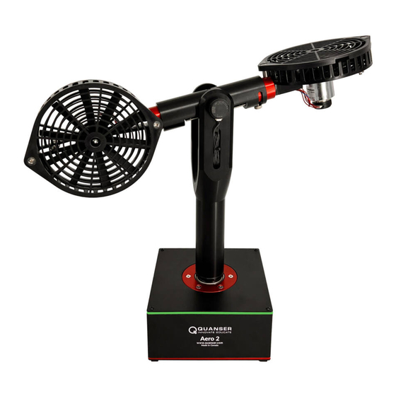
The Quanser Quanser Aero, pictured in Figure 1.1, is a compact dual-rotor two degree-of-freedom aerospace system that can be used to perform a variety of actuator and flight control based experiments. The Quanser Aero can be configured with either the QFLEX 2 USB or QFLEX 2 Embedded interface modules. The QFLEX 2 USB allows control by a computer via USB connection. -
Page 5: System Hardware
(DAQ) device block, the motor position encoders are connected to Encoder Input (EI) channels #0 and #1. EI2 reads the pitch angle of the Aero body, and EI3 reads the yaw angle of the yoke. The Analog Output (AO) channels are connected to the power amplifier command, which then drives the DC fan motors. - Page 6 Figure 2.2: Quanser Aero components 2.2.1 DC Motor The Quanser Aero includes two direct-drive 18V brushed DC motors. The motor specifications are given in Table 2.2. The Quanser Aero incorporates the Allied Motion CL40 Series Coreless DC Motor model 16705. The complete...
- Page 7 2.2.6 Pitch and Motor Position Encoders The encoders used to measure the pitch of the Aero body and the angular position of the DC motorson the Quanser Aero is a single-ended optical shaft encoder. It outputs 2048 counts per revolution in quadrature mode (512 lines per revolution).
-
Page 8: Environmental
The Quanser Aero is equipped with an external DC power supply which provides power for the sensors and motors. This supply is intended for use with 100-240 VAC at 50-60 Hz. Only the provided power supply and AC cord should be used with the Quanser Aero. The included supply is an Adapter Technology Co Ltd model ATS065-P241. -
Page 9: System Parameters
• Marked degree of protection to IEC 60529: Ordinary Equipment (IPX0) 2.4 System Parameters Table 2.2 lists and characterizes the main parameters associated with the Quanser Aero. Symbol Description Value DC Motor Nominal input voltage 18.0 V τ Nominal torque 22.0 mN-m... -
Page 10: System Setup
1. The Quanser Aero should have one of the included sets of propellers installed. If the other propellers are required, follow the procedure for exchanging propellers in Section 3.6 before connecting power. 2. Connect USB 2.0 cable from back cover of Quanser Aero to an enabled USB 2.0 port on your desktop PC or laptop. -
Page 11: Qflex 2 Embedded Hardware Setup
Before opening the Quanser Aero case, ensure that both you and the workspace are properly grounded. 3. Remove the four screws at the corners of the QFLEX panel to release the panel from the Aero chassis. The Quanser Aero is shown in Figure 3.1 below with the screws removed. -
Page 12: Changing Thruster Orientation
4. Disconnect the Aero internal data cable from the QFLEX panel by depressing the latching tab. 5. Connect the Aero internal data cable to the QFLEX panel to be installed, pressing the connector into the socket until a click is heard and the connector latches in place. - Page 13 (a) Hex key inserted in thruster rotation lock (b) Thruster rotated Figure 3.2: Quanser Aero propeller change steps 4. Insert a small hex key or similar object (not provided) through the cap of the propeller hub as shown in Figure 3.3a.
-
Page 14: Pitch And Yaw Locks
3.7 Pitch and Yaw Locks To lock the pitch of the Aero body, use the included hex key to tighten the pitch lock screws as shown in Figure 3.4a To lock the yaw of the yoke, remove the hex key from its storage location in the bottom of the yoke and reinsert it with the long arm of the key down as shown in Figure 3.4b. - Page 15 Quanser aerospace and unmanned systems for teaching and research 3 DOF Helicopter 2 DOF Helicopter 3 DOF Hover QBall 2 Unmanned Vehicle Systems Lab These systems allow you to study or research traditional and modern controls applications relating to spacecraft, unmanned vehicles, rescue missions and autonomous control. For more information please contact info@quanser.com...
Need help?
Do you have a question about the Aero and is the answer not in the manual?
Questions and answers