
Related Manuals for Nortek EC Series


Summary of Contents for Nortek EC Series
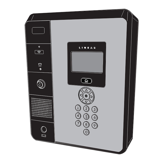
- Page 1 EC / EN Series E3 Entry Install Manual (EN-2A4) (EN-2A7) EC and EN Series Hardware Installation Manual...
-
Page 2: Table Of Contents
Table of Contents Introduction . . . . . . . . . . . . . . . . . . . . . . . . . . . . . . . . . . . . . . . . . . . . . . . . . . . . . . . . . . . . . . . . . . . . . . . . . . . . . . . . . . . . . . . . .1 Feature Overview . -
Page 3: Introduction
The EC Series is network ready, but it can’t interconnect to other EC / EN or EXN modules. The EN Model can be interconnected (one database) to a controlling LAN hub via an Ethernet cable. -
Page 4: Feature Overview
Feature Overview Hardware Features Relay Outputs • FOUR FORM “C” (NO & NC) RELAYS Two 3-amp dry contact Form-C SPDT relay outputs are provided to activate Each relay has 3-amp @ 24-volt rating access devices, such as door strikes, magnetic locks, automatic doors, Two assigned for lock functions barrier gates, and automatic sliding gates. -
Page 5: Installation Overview Checklist
Installation Overview Checklist The following list outlines the steps required for successfully installing an EC / EN Series Telephone Entry System unit. Mount the enclosure ❒ Add up power consumption of all devices connected to system for Power Load Calculation ❒... -
Page 6: System Diagnostics
System Diagnostics LED indicators on the I/O Board and CPU Board are for monitoring the system during operation. When calling for technical assistance, the Technical Services Department may ask the installer to use these indicators to diagnose the system. I/O Board & Modem Indicators 33 LED indicators are on the I/O Board. -
Page 7: Accessory Overview
Accessory Overview Wiegand Devices The two WIEGAND format inputs are available to connect WIEGAND devices. TELEPHONE ENTRY Virtually all 26 through 64 bit WIEGAND output devices from other manufacturers TELEPHONE ENTRY & ACCESS CONTROL & ACCESS CONTROL can be used with EC / EN Series units. SYSTEM SYSTEM SINGLE-GANG... -
Page 8: Component Locations
Component Locations 1 . Optional Camera 24 . Lan Port 2 . Microphone 25 . Not Used 3 . Optional Proximity Sensor 26 . Postal Lock Switch 4 . TTY Jack 27 . Tamper Input 5 . Cabinet Lock 28 . Postal Lock Input 6 . -
Page 9: Wiring Diagram
Wiring Diagram Device Ground: Connect to Earth Ground Rod Device Ground: Connect to Earth Ground Rod Device Ground: Connect to Earth Ground Rod Device Ground: Connect to Earth Ground Rod ENTRY "IN" WEIGAND 2 EXIT "OUT" WEIGAND 2 ENTRY "IN" WEIGAND 1 EXIT "OUT"... -
Page 10: Mounting Requirements For Ec / En Series Units
Mounting Requirements for EC / EN Series Units The EC / EN Series Telephone Entry & Access Control System can be installed for public or private use. The mounting requirements will vary depending on the installation. Review the following information before beginning the installation. Mounting Environment Consider the environmental factors at the desired mounting location. -
Page 11: Entry System Mounting
Entry System Mounting SURFACE The unit’s cabinet is designed to be mounted two ways: MOUNTING • The unit can be mounted directly to a wall or flat surface. • The unit can be mounted on a standard gooseneck pedestal. MARK THE (4) FOUR Choose a well lit location near the controlled opening. - Page 12 Pedestal Mounting The cabinet can be mounted on a gooseneck pedestal. Two pedestals are available: Model GNC-1 is for surface mounting with concrete fasteners, Model GNB-1 is for burial mounting. The EC / EN Series units are designed for installation directly to goose neck mounts. No unique mounting plates are required.
- Page 13 Mount to a Wood Surface Using Pedestal Mounting Holes The cabinet can be mounted to a wood surface using the holes designed to install the Pedestal. 1 . Work with the dealer to identify a stud or reinforcement beam where the housing may be attached.
-
Page 14: System Output Overview
System Output Overview The unit has two door lock relays and two auxiliary output relays that can be activated in response to reader activity, time schedules, or input conditions. All relays are Form-C SPDT and provide non-powered dry contacts rated for 5 Amps. Power for the relay loads can come from an external power supply or from an optionally installed Power Distribution Module board. - Page 15 Door Strike 1 . Install a low voltage electric door strike as a locking device for the door or pedestrian gate. 2 . Install the power supply or transformer for the locking device. DO NOT POWER THE UNIT FROM THIS POWER SUPPLY . 3 .
- Page 16 Mag Lock 1 . Install a low voltage electric magnetic lock as a locking device for the door or pedestrian gate. 2 . Install the power supply or transformer for the locking device. DO NOT POWER THE UNIT FROM THIS POWER SUPPLY . 3 .
-
Page 17: System Input Wiring
System Input Wiring Systems have the three types of switch inputs used for monitoring door position (DSM), exit requests (REX), and auxiliary requests. All inputs are assigned default features that can be configured as needed. The following table shows the default states for each of the inputs: INPUT DEFAULT STATE DOOR SWITCH MONITOR... - Page 18 Request-to-Exit (REX) Inputs The two door relay outputs have REX input terminals. Grounding a REX terminal will request activation for the associated relay. Exit request inputs are typically used with push bars, loop sensors, or pushbuttons. 1 . Install the pushbutton or device to signal an exit request. 2 .
-
Page 19: Wiegand Accessories
Wiegand Accessories The unit’s four Wiegand inputs (WIEGAND #1 IN/OUT & WIEGAND #2 IN/OUT) can be connect to Wiegand output accessories capable of reading up to 64 bit formats. The Wiegand format is a common standard for access control equipment. A typical application would be to add swipe card or proximity readers to the system. -
Page 20: Telephone Wiring
Telephone Wiring For telephone entry applications, the unit connects two wire POTs and/or VOIP telephone lines: 24 and 48 volts. Important Telephone Wiring Tips • WIRING SHOULD BE PLACED IN SEPARATE JACKETED CABLES FOR TELEPHONE AND AC . Route all telephone wires inside a dedicated conduit that is at least six inches away from any AC line wiring. -
Page 21: Operational Postal Lock
Operational Postal Lock A postal lock can be installed in the EC / EN Series unit to provide keyed access for the postal service. The unit’s case is designed to accept a U.S. Postal Service postal lock. When the postal lock is engaged, the programmed output relay will activate. Postal Lock Installation 1 . -
Page 22: Optional Card Reader Mounting
Optional Card Reader Mounting A card reader can be installed inside the EC / EN Series unit. Using a built-in card reader saves the time and expense of installing a stand-alone card reader next to the controlled access point. The user presents their credential directly to the unit’s front panel. The unit is designed to accept mounting of a card reader. - Page 23 STEP 1: Power & Ground Wiring The unit requires power from a 11-13 volt DC power source. WARNING: Do not connect to an AC receptacle controlled by a switch. NOTE: If the unit is powered directly from the plug-in power supply, a separate power supply MUST be used for door locks and accessories. Recommended is the Power Distribution Module (PDM) (optional-not included).
- Page 24 STEP 2: Network Installation Options / Connections An access control network allows shared programming and user information between systems. Networks make system programming and facility management much easier in multi-unit installations. The EC / EN Series Telephone Entry & Access Control System is designed to be compatible with each other when residing in a multi-unit network operating environment.
- Page 25 STEP 3: Ethernet LAN Connection The EC / EN Series Telephone Entry & Access Control System connects to a controlling LAN via an Ethernet connection on the CPU. Previous Telephone Entry Systems utilized the RS-485 cable connection via a “daisy-chain” to connect multiple units. This type of connection is obsolete and current EC / EN Series units do not require linked type connections to communicate with the LAN.
- Page 26 STEP 4: Configuring for a Local Area Network The unit must be located in a trusted network environment where a protected network security system (firewall, etc.) is installed and maintained. CAUTION: The system is exposed to potential risks if installed on a network without proper security precautions. Consult the appropriate on-site IT administrator.
-
Page 27: Cpu Board Indicators
CPU Board Indicators Six LED indicators are on the CPU Board. Refer to the figure for the location of each indicator. • RECEIVE DATA lights when data is received from an external I/O board. • RESET lights an external I/O board reset. •... -
Page 28: Internal Controls
Internal Controls I/O board Pushbuttons Six pushbuttons are on the I/O Board. Refer to the figure for the location of each pushbutton. The LOCK / AUX relays can activate Construction Mode, which allows for manual control of doors and gates to keep them open during heavy construction or other high level traffic. •... -
Page 29: Dimensional Drawing - Ec / En - 2M4
EN-2A4 Dimensional Drawing – EC / EN - 2M4 3 1/2" 13" 16 1/4"... -
Page 30: Dimensional Drawing - Ec / En - 2M7
EN-2A7 Dimensional Drawing – EC / EN - 2M7 3 1/2" 13" 16 1/4"... -
Page 31: Troubleshooting
Troubleshooting System completely dead • No power from power supply. Check voltage at power supply terminals. • Check voltage at I/O Board power terminals. Buzz on speaker • Check for telephone line shorted to ground. • Verify that telephone wires are twisted pair. •... -
Page 32: Specifications
Specifications MECHANICAL Case dimensions: 13” W x 16-1/4” H x 3-1/2” D Feature Levels ELECTRICAL Voltage: 11V-13V Volts DC Current: 750 mA Destructive Attack Level II Outputs: Four Relays (2 Portal, 2 Aux) Form “C” 5 Amps @ 24 Volts maximum Inputs: Two DSM door position inputs Two REX exit request inputs Ethernet Line Security... - Page 33 Requesting Access with a Visitor Call • Navigate to Resident Directory using Navigation keys. • Scroll through the alphabet to the first letter of the last name. • Press Enter. • Scroll through name list to desired entry. • Press Enter to call. •...
-
Page 34: Limited Warranty
LLC does not warrant this product to consumers . Consumers should inquire from their selling dealer as to the nature of the dealer’s warranty, if any. There are no obligations or liabilities on the part of Nortek Security & Control LLC for consequential damages arising out of or in connection with use or performance of this product or other indirect damages with respect to loss of property, revenue, or profit, or cost of removal, installation, or reinstallation.
Need help?
Do you have a question about the EC Series and is the answer not in the manual?
Questions and answers