Table of Contents
Advertisement
Quick Links
Download this manual
See also:
User Manual
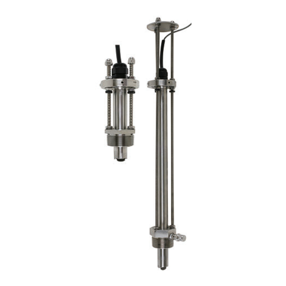
Signet 2540 High Performance Flow Sensor
*3-2540.090*
3-2540.090
Rev. 10
•
English
•
Deutsch
•
Français
•
Español
•
Português
•
Italiano
中文
•
01/19
Location of Fitting
Recommended sensor upstream/downstream mounting requirements.
Inlet
Flange
10x I.D.
Valve/Pump
50x I.D.
Sensor Mounting Position
Vertical mounting is recommended for best
overall performance. Mount at a maximum of
30° when air bubbles are present.
DO NOT mount on the bottom of the pipe
when sediments are present.
Table of Contents
Warranty Statement .............................................................................. 2
Product Registration ............................................................................. 2
Safety Information................................................................................. 2
Dimensions ........................................................................................... 2
Specifi cations........................................................................................ 3
Sensor Wiring ....................................................................................... 3
Electronics Module Installation and removal ........................................ 4
Installation............................................................................................. 5
Calculating the H Dimension ................................................................ 6
Standard and Hot-Tap Sensor Installation ............................................ 7
Standard Sensor Removal.................................................................... 8
Hot-Tap Sensor Removal...................................................................... 9
Maintenance ......................................................................................... 9
K-Factors ............................................................................................ 10
Ordering Information ........................................................................... 12
Operating Instructions
Pipe fi ttings MUST be installed by a certifi ed
welder only. GF Signet will not assume liability
of any kind for improper fi tting installations.
Outlet
Reducer
15x I.D.
5x I.D.
2 x 90° Elbow
3 dimensions
5x I.D.
40x I.D.
90° Elbow
5x I.D.
20x I.D.
2 x90° Elbow
5x I.D.
25x I.D.
0°
30°
+30°
-
Process Pipe
English
5x I.D.
5x I.D.
Advertisement
Table of Contents

Subscribe to Our Youtube Channel
Related Manuals for GF Signet 2540


Summary of Contents for GF Signet 2540
-
Page 1: Table Of Contents
Rev. 10 01/19 Operating Instructions Location of Fitting Pipe fi ttings MUST be installed by a certifi ed welder only. GF Signet will not assume liability of any kind for improper fi tting installations. Recommended sensor upstream/downstream mounting requirements. Inlet Outlet 90°... -
Page 2: Warranty Statement
Service Form and goods must be specifi cations, characteristics of the measured fl uid, and returned to your local GF Sales offi ce or distributor. installation details. These can include, but are not limited Product returned without a Service Form may not be to: process fl... -
Page 3: Specifi Cations
Pressure/temperature specifi cations refer to sensor performance in water. Certain chemical limitations may apply. Chemical compatibility should be verifi ed. manufactured date code = mm/yy ex. 04/08 04 - month of April 04/08 08 - year 2008 Signet 2540 High Performance Flow Sensor... -
Page 4: Electronics Module Installation And Removal
Liquid Tight Connector-Cap w/ ½ in. NPT threads Grip the electronics module at rubber strain relief Electronics Module 3-2541.260-1 (for Standard sensor) 3-2541.260-2 (for Hot-tap sensor) ½ in. NPT Threads Signet 2540 High Performance Flow Sensor... -
Page 5: Installation
(1.50 x 2 in.) long sensor fitting process pipe (side view) process pipe pipe fitting Fig. 2 pipe sealant recommended sensor fitting bleed valve Fig. 1 make sure bleed valve clears isolation valve handle process pipe Fig. 3 Signet 2540 High Performance Flow Sensor... -
Page 6: Calculating The H Dimension
13.490 13.390 13.458 13.440 ----- ----- 13.140 12.840 13.290 13.190 13.240 13.216 ----- ----- 12.915 12.565 13.090 12.990 13.040 13.016 ----- ----- ----- 12.290 12.890 12.790 12.816 12.790 ----- ----- 12.440 12.015 12.690 12.590 Signet 2540 High Performance Flow Sensor... -
Page 7: Standard And Hot-Tap Sensor Installation
E. Make sure the bleed valve is closed 18 inch 359 mm (14.14 in) (full clockwise position). threaded rods sensor fitting bleed valve direction of flow process pipe (side view) Fig. 9 Signet 2540 High Performance Flow Sensor... -
Page 8: Standard Sensor Removal
fl ange. Pull up on sensor fl ange with twisting motion. " " H isolation valve direction of flow Fig. 12 protector plate cap nuts protector plate protector plate hex nut Fig. 13 Signet 2540 High Performance Flow Sensor... -
Page 9: Hot-Tap Sensor Removal
Note: A hammer and center clearance hole inward. Only punch can also be used if a install one retainer at this time. clamp or vise is not available. Signet 2540 High Performance Flow Sensor... -
Page 10: K-Factors
263.85 generated by the 2540 paddlewheel per unit of U.S. gallons pounds of water 0.120 liquid in a specifi c pipe size. U.S. gallons acre feet 325853 U.S. gallons Imperial gallons 1.201 Signet 2540 High Performance Flow Sensor... - Page 11 15.835 4.184 6 in. 9.8630 2.606 6 in. 11.041 2.917 8 in. 5.6400 1.490 8 in. 6.2877 1.661 10 in. 3.4476 0.911 10 in. 3.8529 1.018 12 in. 2.3786 0.628 12 in. 2.6407 0.698 Signet 2540 High Performance Flow Sensor...
-
Page 12: Ordering Information
Ordering Information Signet 3-2540-XX Stainless Steel High Performance fl ow sensor with removable electronics Mfr. Part No. Code Description 3-2540-1 198 840 035 1½ inch NPT thread, Tungsten Carbide rotor 3-2540-2 198 840 036 1½ inch ISO thread, Tungsten Carbide rotor 3-2540-3 198 840 037 1½...
Need help?
Do you have a question about the Signet 2540 and is the answer not in the manual?
Questions and answers