Table of Contents
Advertisement
Quick Links
INSTALLATION AND MAINTENANCE INSTRUCTIONS
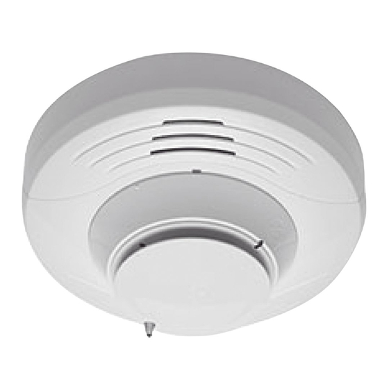
SK-FIRE-CO-W
Multi-Criteria CO and Smoke Sensor
SPECIFICATIONS
Operating Voltage Range:
Operating Current @ 24 VDC:
Maximum Alarm Current:
Maximum Current:
Operating Humidity Range:
Operating Temperature Range:
Air Velocity:
Height:
Diameter:
Weight:
Isolator Load Rating:
*Please refer to your isolator base/module manual for isolator calculation instructions.
UL 2075 listed for Carbon Monoxide
UL 268 listed for Open Air Protection
UL 521 listed for Heat Detectors
This sensor must be installed in compliance with the control panel sys-
tem installation manual. For local audible indication of a fire and/or
carbon monoxide alarm, it is recommended to install the multi-criteria
carbon monoxide (CO) and smoke sensors into a B200S series sounder
base. If a local audible device is not used, care should be taken to de-
velop a proper response plan. The installation must meet the require-
ments of the Authority Having Jurisdiction (AHJ). Sensors offer maximum
performance when installed in compliance with the National Fire Protec-
tion Association (NFPA); see NFPA 72 and NFPA 720. For a complete list
of compatible bases, refer to the Base/Sensor Cross Reference Chart at
systemsensor.com.
GENERAL DESCRIPTION DOES THIS SUPPORT CLIP MODE
Model SK-FIRE-CO-W is a plug-in type multi-criteria smoke sensor that offers
a photoelectric sensing chamber combined with a carbon monoxide (CO) sen-
sor, 135°F (57.2°C) fixed temperature heat detector and infrared (IR) sensors,
as well as a carbon monoxide detector. The SK-FIRE-CO-W also transmits an
alarm signal due to heat (135°F/57.2°C) per UL 521.
All sensors transmit an analog representation of smoke and/or carbon monox-
ide density over a communication line to a control panel. Rotary dial switches
are provided for setting the sensor's address. (See Figure 2.)
Two LEDs on the sensor are controlled by the panel to indicate sensor status.
An output is provided for connection to an optional remote LED annunciator
(P/N RA100Z).
Silent Knight panels offer different features sets across different models. As a
result, certain features of the photoelectric sensors may be available on some
control panels, but not on others.
The multi-criteria CO and smoke sensors only support SK protocol systems.
The possible features available in the multi-criteria CO and smoke sensors, if
supported by the control unit are:
1.
The sensor's LEDs can operate in three ways—on, off, and blinking—and
they can be set to red, green, or amber. This is controlled by the panel.
2.
The remote output may be synchronized to the LED operation or con-
trolled independent of the LEDs.
3.
Devices are point addressable up to 159 addresses.
Please refer to the operation manual for the UL listed control panel for specific
operation. The photoelectric sensors require compatible addressable com-
munications to function properly. Connect these sensors to listed-compatible
control panels only.
SPACING
Silent Knight recommends spacing sensors in compliance with NFPA 72. In
low air flow applications with smooth ceilings, space sensors 30 feet apart
(9.1 m). For specific information regarding sensor spacing, placement, and
15 to 32 VDC
200 uA (one communication every 5 seconds with green LED blink on communication)
2 mA @ 24 VDC (one communication every 5 seconds with red LED solid on)
4.5 mA @ 24 VDC (one communication every 5 seconds with amber LED solid on)
15% to 90% Relative Humidity, Non-condensing
32°F to 100°F (0°C to 38°C)
0 to 4000 ft./min. (0 to 1219.2 m/min.)
2.7˝ (69 mm) installed in B200S series sounder base
6.875˝ (175 mm) installed in B200S series sounder bases
3.4 oz. (95 g)
0.0063*
12 Clintonville Road, Northford, CT 06472-1610
Special Applications, refer to NFPA 72 or the System Smoke Detector Applica-
tion Guide, available from Silent Knight.
WIRING GUIDE
All wiring must be installed in compliance with the National Electrical Code,
applicable local codes, and any special requirements of the Authority Having
Jurisdiction. Proper wire gauges should be used. The installation wires should
be color-coded to limit wiring mistakes and ease system troubleshooting.
Improper connections will prevent a system from responding properly in the
event of a fire.
Remove power from the communication line before installing sensors.
1.
Wire the sensor base (supplied separately) per the base wiring diagram.
(See Figure 1.)
2.
Set the desired address on the sensor address switches. (See Figure 2.)
3.
Install the sensor into the sensor base. Push the sensor into the base
while turning it clockwise to secure it in place.
4.
After all sensors have been installed, apply power to the control panel
and activate the communication line.
5.
Test the sensor(s) as described in the TESTING section of this manual.
FIGURE 1. WIRING DIAGRAM
REMOTE
ANNUNCIATOR
+
-
(+)
2
1
3
(–)
(–)
CLASS A OPTIONAL WIRING
(+)
Do not loop wire under terminal 1 or 2. Break wire run to provide supervision
of connections.
FIGURE 2. ROTARY ADDRESS SWITCHES
7
8
6
5
4
3
2
1 0
15
TENS
1
Phone: 203-484-7161 Fax: 203-484-7118
www.silentknight.com
2
1
3
3
CAUTION
7
8
9
6
9
10
5
11
4
12
3
13
2
14
1 0
ONES
I56-6602-000
2
1
C0129-04
C0162-00
2/21/2019
Advertisement
Table of Contents

Related Manuals for Honeywell SK-FIRE-CO-W


Summary of Contents for Honeywell SK-FIRE-CO-W
- Page 1 135°F (57.2°C) fixed temperature heat detector and infrared (IR) sensors, and activate the communication line. as well as a carbon monoxide detector. The SK-FIRE-CO-W also transmits an Test the sensor(s) as described in the TESTING section of this manual.
- Page 2 TAMPER RESISTANCE A hair dryer of 1000-1500 watts should be used to test the thermistors. Model SK-FIRE-CO-W includes a tamper-resistant capability that prevents re- Direct the heat toward the thermistor, holding the heat source approxi- moval from the base without the use of a tool. Refer to the base manual for mately 12 inches (30 cm) from the detector in order to avoid damaging details on making use of this capability.
- Page 3 Also young children and pets may be the first to be affected. required continue with Step 4, otherwise skip to Step 7. Per UL standard 2075, the SK-FIRE-CO-W has been tested to the sensitivity Remove the chamber cover/screen assembly by pulling it straight out.
- Page 4 – Consult the dealer or an experienced radio/TV technician for help. in information disclosure, spoofing, and integrity violation. Silent Knight ® is a registered trademark of Honeywell International, Inc. Testifire ® and SOLO ® are registered trademarks of SDi, LLC.
Need help?
Do you have a question about the SK-FIRE-CO-W and is the answer not in the manual?
Questions and answers