Table of Contents
Advertisement
FAA Approved Installation Manual for the
EDM-900 and EDM-930
Primary Engine Data Management System
1.
Revisions ______________________________________________________________________________________ 2
2.
Read This First _________________________________________________________________________________ 2
3.
Instrument Labeling______________________________________________________________________________ 3
4.
Operation and Abbreviations ______________________________________________________________________ 4
5.
Locating and Installing the Indicator and Remote Alarm Display (RAD and Alert Light) ________________________ 8
6.
EDM-900/930 Key information installation __________________________________________________________ 10
7.
Routing the Wiring Harnesses _____________________________________________________________________ 11
8.
Power Connection ______________________________________________________________________________ 11
9.
Probe Wiring __________________________________________________________________________________ 12
10.
Wiring Markings _______________________________________________________________________________ 12
11.
Exhaust Gas Temperature Probe (EGT) Installation ___________________________________________________ 12
12.
Engine EGT_____________________________________________________________________________ 13
13.
Turbine Inlet Temperature (TIT) Probe Installation (optional) ___________________________________________ 13
14.
Cylinder Head Temperature (CHT) Probe Installation__________________________________________________ 14
15.
Radial Engine CHT (spark plug gasket) _____________________________________________________________ 14
16.
Outside Air Temperature (OAT) Probe Installation ____________________________________________________ 14
17.
Induction Air (IAT), Compressor Discharge Temperature Probe Install (optional) ____________________________ 14
18.
Carburetor Probe Installation (optional) ____________________________________________________________ 15
19.
Oil Temperature Probe Installation ________________________________________________________________ 15
20.
Oil Pressure Sensor Installation ___________________________________________________________________ 15
21.
Fuel Pressure Sensor Installation __________________________________________________________________ 16
22.
Ammeter Shunt Installation _______________________________________________________________________ 18
23.
General Fuel Flow Transducer Installation __________________________________________________________ 19
24.
Fuel Level Sender Wiring Types ___________________________________________________________________ 20
25.
Fuel Flow Totalizer, Refuel Question _______________________________________________________________ 26
26.
GPS Interface _________________________________________________________________________________ 27
27.
Manifold Pressure (MAP) Sensor __________________________________________________________________ 27
28.
RPM Sensor installation _________________________________________________________________________ 29
29.
EDM-900/930 Specifications and Limitations_________________________________________________________ 30
30.
EMI Radio Test and functional check:_______________________________________________________________ 31
31.
Component Parts _______________________________________________________________________________ 32
32.
Weight and Balance Data ________________________________________________________________________ 33
33.
Pilot Programming _____________________________________________________________________________ 34
34.
Programming the HP Constant ____________________________________________________________________ 35
35.
Programming the MAP __________________________________________________________________________ 35
36.
Selecting Fuel Pressure Type (EDM-900 only) ________________________________________________________ 35
37.
Customizing Non-Primary Data (EDM900 only) ______________________________________________________ 36
38.
K Factor______________________________________________________________________________________ 36
39.
Fine tuning the K Factor _________________________________________________________________________ 37
40.
Adjusting the K Factor___________________________________________________________________________ 38
41.
Programming Accumulate Trip Total _______________________________________________________________ 38
42.
Trouble Shooting _______________________________________________________________________________ 39
Connector Pin Assignments on EDM, J1 through J5 _______________________________________________ 41
43.
44.
Connector Pin Assignments on EDM, J1 through J5 ___________________________________________________ 42
45.
J3 RPM, MP, Oil-P_____________________________________________________________________________ 45
46.
Appendix A Fuel Flow install Report 503 ___________________________________________________________ 49
47.
Appendix B ICA _______________________________________________________________________________ 49
Appendix C Connector Pin Assignments on EDM, J1-J2 Only with ARINC 429 _____________________________ 50
48.
The Owner of the EDM-900/930 must keep this manual
TABLE OF CONTENTS
J.P. INSTRUMENTS
PO BOX 7033
HUNTINGTON BEACH CA
Report No 908
Page 1 of 56 Rev I
Date 1-18-2013
Last printed 1/22/2013 10:53:00 AM
Advertisement
Table of Contents
Troubleshooting

Related Manuals for J.P. Instruments EDM-900


Summary of Contents for J.P. Instruments EDM-900
-
Page 1: Table Of Contents
Appendix A Fuel Flow install Report 503 ___________________________________________________________ 49 Appendix B ICA _______________________________________________________________________________ 49 Appendix C Connector Pin Assignments on EDM, J1-J2 Only with ARINC 429 _____________________________ 50 The Owner of the EDM-900/930 must keep this manual J.P. INSTRUMENTS PO BOX 7033... -
Page 2: Revisions
The instrument must be grounded at the engine, not at the avionics ground. Record the installation of the EDM-900 or EDM-930 on a FAA form 337. Make an entry in the aircraft logbook. Note: Removal of probes, sensors and the instrument is the reverse of the installation procedure. -
Page 3: Instrument Labeling
Percent of HP Quantity Example PN 790000-(X)-(XXX) (X) denotes EDM-900 or EDM-930, (XXX) denotes Part Number for a specific aircraft with or without and engine STC. Each PN is specific to a Make and Model Aircraft with or without STC. In which the information is gathered from the Aircraft POH or STC Data sheet. -
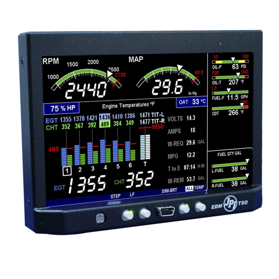
Page 4: Operation And Abbreviations
Date 1-18-2013 4. Operation and Abbreviations The EDM-900/930 is a combined electronic indicating system which simultaneously displays to the pilot powerplant and aircraft systems operating parameters. It includes the following indicating systems; replacing all previous primary digital and/or analog instruments: Message Area Abbreviation in parenthesis. (X)* denotes cylinder No. - Page 5 Remote Alarm Light EDM 900 The remote alarm light is a Red or Yellow light depending on the alarm condition. The EDM-900 incorporates a single light that alerts the pilot that a problem existing within the engine. This light is place in with the primary flight instruments and required only if the display is more than 8 inches from the center of the instrument “T”...
-
Page 6: Faa Approved Installation Manual For The Report No
FAA Approved Installation Manual for the Report No 908 EDM-900 and EDM-930 Page 6 of 56 Rev I Primary Engine Data Management System Date 1-18-2013 EDM-930 Display... - Page 7 Landscape Mode EDM-900 system mounts in a 3.125 inch diameter instrument panel hole in either a portrait or landscape position depending on panel hole location. By holding the Step button ( first on left) for approx. 10 seconds and arrow will appear on the display showing which way the rotation will use as up.
-
Page 8: Locating And Installing The Indicator And Remote Alarm Display (Rad And Alert Light)
Single Engine Aircraft EDM-900/930 A) The EDM-900/930 display should be located as close as possible to the pilot with an unobstructed view and for easy access to the buttons on the instrument. The least desirable view angle is landscape looking up. - Page 9 Page 9 of 56 Rev I Primary Engine Data Management System Date 1-18-2013 Mounting bracket for the EDM-900 EDM-900 Model: Mounts in a standard 3.1/8” instrument hole. First, place the mounting bracket on the instrument and tighten the clamp hex screw until you can just remove the instrument from the bracket. The Mounting bracket is then placed behind the instrument panel hole and screwed (6-32 x ½”...
-
Page 10: Edm-900/930 Key Information Installation
Aircraft specific configuration information is loaded differently on both the EDM-900 and the EDM-930. The configuration data is the same for both instruments. The data for the EDM-900/930 is loaded via the mini USB port on the EDM-900 and a standard USB port for the EDM-930. -
Page 11: Routing The Wiring Harnesses
FAA Approved Installation Manual for the Report No 908 EDM-900 and EDM-930 Page 11 of 56 Rev I Primary Engine Data Management System Date 1-18-2013 Be sure to verify that this matches your aircraft. Note: If your EDM should ever have to be replaced with a different unit, the factory will reprogram it to match your configuration. -
Page 12: Probe Wiring
The most common installation problems are related to poor quality terminations. 10. Wiring Markings The EDM-900/930 is supplied with special Teflon insulated Chromel Alumel factory assembled wiring harness configured for the correct number of cylinders. The wire harness is marked E1= EGT-1, C1= CHT-1, etc. -
Page 13: Radial Engine Egt
FAA Approved Installation Manual for the Report No 908 EDM-900 and EDM-930 Page 13 of 56 Rev I Primary Engine Data Management System Date 1-18-2013 The Model M-111 Probe will fit any engines where the existing holes in the exhaust stack are 1/8" to 1/4"... -
Page 14: Cylinder Head Temperature (Cht) Probe Installation
If you choose to use only the EDM-900/930 TIT display you may remove the factory installed TIT indicator and leave the TIT probe installed. Connect the JPI wire marked TIT directly to the probe noting color polarity. The TIT probe should now have only the JPI leads attached to it. -
Page 15: Carburetor Probe Installation (Optional)
FAA Approved Installation Manual for the Report No 908 EDM-900 and EDM-930 Page 15 of 56 Rev I Primary Engine Data Management System Date 1-18-2013 18. Carburetor Probe Installation (optional) Use the J1 connector harness 790200 and insert the yellow wire into the connector pin 5 and the red wire into pin 6. -
Page 16: Fuel Pressure Sensor Installation
FAA Approved Installation Manual for the Report No 908 EDM-900 and EDM-930 Page 16 of 56 Rev I Primary Engine Data Management System Date 1-18-2013 Alternate method of installation keeping the original sensors in the aircraft operational 20.1 The oil pressure sensor should tee off the oil pressure line feeding the original aircraft gauge or the oil pressure switch is removed and the sender is installed in that location. - Page 17 FAA Approved Installation Manual for the Report No 908 EDM-900 and EDM-930 Page 17 of 56 Rev I Primary Engine Data Management System Date 1-18-2013 21.1 Adding a non-primary gauge to the system Requirements: new generation EDM-930 with software from June 2010 or later...
-
Page 18: Ammeter Shunt Installation
FAA Approved Installation Manual for the Report No 908 EDM-900 and EDM-930 Page 18 of 56 Rev I Primary Engine Data Management System Date 1-18-2013 22. Ammeter Shunt Installation Use the J5 connector harness 790719-X labeled AMP+ and AMP-. Connect the harness leads using ring terminals to the smaller terminal screws on the side of the shunt. -
Page 19: General Fuel Flow Transducer Installation
AE102/62-24 pump. The EDM-900/930 fuel flow transducer receives signal from any installed 201 or 231 transducer with either of these part numbers embossed on to the top of the transducer. For specific engine Installations see Appendix A Report 503... -
Page 20: Fuel Level Sender Wiring Types
FAA Approved Installation Manual for the Report No 908 EDM-900 and EDM-930 Page 20 of 56 Rev I Primary Engine Data Management System Date 1-18-2013 24. Fuel Level Sender Wiring Types The EDM has the capability to interface to the aircraft’s fuel level system. It is also used to directly read the fuel senders for fuel calibration (no other equipment is needed). - Page 21 FAA Approved Installation Manual for the Report No 908 EDM-900 and EDM-930 Page 21 of 56 Rev I Primary Engine Data Management System Date 1-18-2013 Example harness arrangement for an aircraft with resistive output senders Resistive Harness PN 790719-3...
- Page 22 FAA Approved Installation Manual for the Report No 908 EDM-900 and EDM-930 Page 22 of 56 Rev I Primary Engine Data Management System Date 1-18-2013 Voltage Output Type Sender System 24.3 Voltage output type systems usually have a convertor box. This is typical with the ‘Pennycap’ brand capacitive sender system.
- Page 23 FAA Approved Installation Manual for the Report No 908 EDM-900 and EDM-930 Page 23 of 56 Rev I Primary Engine Data Management System Date 1-18-2013 EDM as a meter . Getting Started…Collecting Fuel Level Calibration Data using the 1. With power off, hold in Button 4 (Button 1 being far left) and then turn on power. For each EDM monitored tank, create a paper table with the desired number of calibration points (2 to 5) and at what volume each will be.
- Page 24 FAA Approved Installation Manual for the Report No 908 EDM-900 and EDM-930 Page 24 of 56 Rev I Primary Engine Data Management System Date 1-18-2013 24.4.1 After you have collected your data After you have collected your data…Entering / Editing Fuel Level Calibration Data The Fuel Table Editor is a spreadsheet type format allowing you to easily see the volume and related calibration values side by side.
- Page 25 FAA Approved Installation Manual for the Report No 908 EDM-900 and EDM-930 Page 25 of 56 Rev I Primary Engine Data Management System Date 1-18-2013 3. Tap USER when you see ‘Do you want to restore user table?’ (Note: tapping FACTORY causes the fuel table stored on the Key Card to over-write any previous user entries in the fuel table.
-
Page 26: Fuel Flow Totalizer, Refuel Question
FAA Approved Installation Manual for the Report No 908 EDM-900 and EDM-930 Page 26 of 56 Rev I Primary Engine Data Management System Date 1-18-2013 7. Tap TANK to select the next active tank and repeat previous step. Continue until all tanks ‘points’ have been set. -
Page 27: Gps Interface
FAA Approved Installation Manual for the Report No 908 EDM-900 and EDM-930 Page 27 of 56 Rev I Primary Engine Data Management System Date 1-18-2013 1 and 2 again until the display (5 sec.) changes and you see FACTORY . At this point you will see MAIN = XX., adjust with the “Plus and Minus buttons. - Page 28 FAA Approved Installation Manual for the Report No 908 EDM-900 and EDM-930 Page 28 of 56 Rev I Primary Engine Data Management System Date 1-18-2013 MAP SIG- GRN MAP Sensor MAP PWR RED MAP SIG+ WHT connector MAP GND BLK...
-
Page 29: Rpm Sensor Installation
FAA Approved Installation Manual for the Report No 908 EDM-900 and EDM-930 Page 29 of 56 Rev I Primary Engine Data Management System Date 1-18-2013 28. RPM Sensor installation Use the J3 connector harness 790420 and connect the 3 leads using the supplied 3-pin connector and pins. There are three types of magnetos commonly in use. -
Page 30: Edm-900/930 Specifications And Limitations
Primary Engine Data Management System Date 1-18-2013 29. EDM-900/930 Specifications and Limitations The following parameters must be customized for the aircraft into which the EDM-900/930 is installed. Factory set limits or default values for EDM-900/930 1. TIT 1650 F TSO-C43 2. -
Page 31: Emi Radio Test And Functional Check
If unusual noise is heard, remove power from the EDM-900/930 system to check if it is the source of this noise. If the EDM-900/930 system is not the source of ‘unusual noise’ then mark the table with a ‘PASS’. -
Page 32: Component Parts
MAP P/N 159934A Kit 14400 RPM one of P/N 420815-1,-2 RAD P/N-790749 for use with the EDM-930 Alarm light PN 790547 for use with the EDM-900 31.1 Component Parts List for EGT KIT 12800, TIT KIT 120000 1 Thermocouple type K probe PN M-111... -
Page 33: Weight And Balance Data
1 P/N 174402 Connector Pack 3 Pin and Terminals 31.13 Components Parts list for RPM sensor P/N depends on Magneto make and model Bendix magneto -20,1200 P/N 420815-1 Slick magneto 4000 or 6000 P/N 420815-2 31.14 Weight and Balance Data Indicator PN 790000(-A) EDM-900 2.0 Lbs... -
Page 34: Pilot Programming
FAA Approved Installation Manual for the Report No 908 EDM-900 and EDM-930 Page 34 of 56 Rev I Primary Engine Data Management System Date 1-18-2013 Indicator PN 790000(-C) EDM-930 3.0 Lbs EGT / TIT / CDT / IAT / OAT probe 2.0 oz. -
Page 35: Programming The Hp Constant
3. Set the MP and RPM per your POH to 70 percent power. Let conditions stabilize. 4. Change the HP reading on the EDM-900 to 70 percent by adjusting the HP constant in the lower display by holding or tapping the LF button. Percent HP should be close to 100 percent during takeoff at sea level. -
Page 36: Customizing Non-Primary Data (Edm900 Only)
FAA Approved Installation Manual for the Report No 908 EDM-900 and EDM-930 Page 36 of 56 Rev I Primary Engine Data Management System Date 1-18-2013 8. Tap the STEP button repeatedly until the message END? is displayed in the message area Tap the button labeled YES to save changes and restart the EDM. -
Page 37: Fine Tuning The K Factor
1. Make at least three flights of about two to three hours each. Note the actual fuel used (as determined by topping the tanks) and the EDM-900 calculation of the fuel used for each flight USD. Fuel USED shown by EDM... -
Page 38: Adjusting The K Factor
Select “No” if you wish to display total fuel used since the last time you informed the EDM-900 that the aircraft was refueled. Select “Yes” to display total fuel used for an extended trip with multiple fuel stops. This selection affects only measurement. -
Page 39: Trouble Shooting
FAA Approved Installation Manual for the Report No 908 EDM-900 and EDM-930 Page 39 of 56 Rev I Primary Engine Data Management System Date 1-18-2013 41. Trouble Shooting Diagnostic Testing on Startup and During Flight When your EDM is first turned on it tests internal components, calibration and integrity of the probes. - Page 40 FAA Approved Installation Manual for the Report No 908 EDM-900 and EDM-930 Page 40 of 56 Rev I Primary Engine Data Management System Date 1-18-2013 NO 50MV Calibration error. Return unit to factory. NO 2.5V Calibration error. Return unit to factory.
-
Page 41: Connector Pin Assignments On Edm, J1 Through J5
FAA Approved Installation Manual for the Report No 908 EDM-900 and EDM-930 Page 41 of 56 Rev I Primary Engine Data Management System Date 1-18-2013 Connector Pin Assignments on EDM, J1 through J5 Rear view of EDM 930 Showing Connector Locations... -
Page 42: Connector Pin Assignments On Edm, J1 Through J5
FAA Approved Installation Manual for the Report No 908 EDM-900 and EDM-930 Page 42 of 56 Rev I Primary Engine Data Management System Date 1-18-2013 Connector Pin Assignments on EDM, J1 through J5 Rear view of EDM 900 Showing Connector Locations... - Page 43 FAA Approved Installation Manual for the Report No 908 EDM-900 and EDM-930 Page 43 of 56 Rev I Primary Engine Data Management System Date 1-18-2013...
- Page 44 FAA Approved Installation Manual for the Report No 908 EDM-900 and EDM-930 Page 44 of 56 Rev I Primary Engine Data Management System Date 1-18-2013...
-
Page 45: J3 Rpm, Mp, Oil-P
FAA Approved Installation Manual for the Report No 908 EDM-900 and EDM-930 Page 45 of 56 Rev I Primary Engine Data Management System Date 1-18-2013 J3 RPM, MP, Oil-P J-3 Harness with i2s Oil and manifold pressure sender... -
Page 46: Serial Communications
FAA Approved Installation Manual for the Report No 908 EDM-900 and EDM-930 Page 46 of 56 Rev I Primary Engine Data Management System Date 1-18-2013 J4 (FF, GPS, AMP 2 ) Data out to GPS White 1 Serial communications Data in from GPS... - Page 47 FAA Approved Installation Manual for the Report No 908 EDM-900 and EDM-930 Page 47 of 56 Rev I Primary Engine Data Management System Date 1-18-2013 J5 PN 790719 (fuel tanks, fuel press, amps) 44.1 J-5 Harness with i2s fuel pressure sender.
- Page 48 FAA Approved Installation Manual for the Report No 908 EDM-900 and EDM-930 Page 48 of 56 Rev I Primary Engine Data Management System Date 1-18-2013...
-
Page 49: Appendix A Fuel Flow Install Report 503
FAA Approved Installation Manual for the Report No 908 EDM-900 and EDM-930 Page 49 of 56 Rev I Primary Engine Data Management System Date 1-18-2013 45. Appendix A Fuel Flow install Report 503 See attached Report Appendix B See attached Report... -
Page 50: Appendix C Connector Pin Assignments On Edm, J1-J2 Only With Arinc 429
FAA Approved Installation Manual for the Report No 908 EDM-900 and EDM-930 Page 50 of 56 Rev I Primary Engine Data Management System Date 1-18-2013 Connector Pin Assignments on EDM, J1-J2 Only with ARINC 429 47. Appendix C Production J1 - DB25M... - Page 51 EDM-900/930 PRIMARY ENGINE DATA MANAGEMENT SYSTEMS Aircraft as listed on STC SA01435SE This Supplement must be attached to the FAA Approved Installation Manual when the J.P. Instruments EDM-900/930 is installed in accordance with Supplemental Type Certificate SA01435SE. Before performing any procedures contained in this manual the user should verify they have the latest ICA revision.
- Page 52 FAA Approved Installation Manual for the Report No 908 EDM-900 and EDM-930 Page 52 of 56 Rev I Primary Engine Data Management System Date 10-9-2012 Revisions For ICA: Revisio Pages Date Description Affected 12/ 15 /2011 Complete Document 1 thru 6...
- Page 53 Date 10-9-2012 1- Introduction: The EDM-900/930 is a combined electronic indicating system which simultaneously displays to the pilot powerplant and aircraft systems operating parameters. It includes the following indicating systems; replacing all previous primary digital and/or analog instruments: Message Area Abbreviation for primary and non-primary instruments is shown on the Right with the function on the left .
- Page 54 EDM- 930 Remote Alarm Display (RAD)and EDM-900 Remote Annunciator Light (RAL) RAD for the EDM-930 is a 0.2” high, 8 character independent display and for the EDM-900 the RAL is a combination Red/Yellow light. The RAD or RAL will still function if the main display is inoperable. On the EDM-900 and EDM-930 only primary instrument alarms are indicated.
-
Page 55: Servicing Information
900/930. After initial installation follow the maintenance instructions of the ICA to replace failed components. 4- Maintenance Instructions: Visually inspect wiring and all other EDM-900 series components on installation and during scheduled 100 hour and/or annual inspections (as applicable) for damage, wear, and security. Repair or replace wiring as needed and replace components in accordance with the EDM 900/930 Installation Manual, Report No. -
Page 56: Application Of Protective Treatments
FAA Approved Installation Manual for the Report No 908 EDM-900 and EDM-930 Page 56 of 56 Rev I Primary Engine Data Management System Date 10-9-2012 9- Application of Protective Treatments: Not applicable to this system. 10- Data: Not applicable to this system.
Need help?
Do you have a question about the EDM-900 and is the answer not in the manual?
Questions and answers