Table of Contents
Advertisement
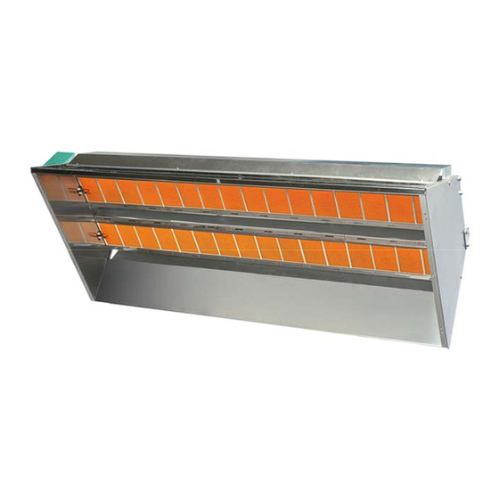
Luminous Infra-red Gas Heaters
MANUAL for INSTALLATION,
RUNNING and MAINTENANCE
Models: 4P, 6P, 8P, 10P, 12PR, 12P, 16P,
4PB, 6PB, 8PB, 10PB, 12PRB, 12PB, 16PB,
10+10P, 12+12P, 16+16P,
10+10PB, 12+12PB, 16+16PB,
10+10PS, 12+12PS, 16+16PS
10+10PSB, 12+12PSB, 16+16PSB
Version "DC and DCeco"
SIABS S.r.l. – ITALY
via Del Lavoro, 7
20010 – Casorezzo (MILAN)
Phone +39 02 90384081
Fax
+39 02 9029538
E-mail
commerciale@siabs.it
Web page
www.siabs.com
Advertisement
Table of Contents

Related Manuals for Siabs 4P


Summary of Contents for Siabs 4P
- Page 1 Luminous Infra-red Gas Heaters MANUAL for INSTALLATION, RUNNING and MAINTENANCE Models: 4P, 6P, 8P, 10P, 12PR, 12P, 16P, 4PB, 6PB, 8PB, 10PB, 12PRB, 12PB, 16PB, 10+10P, 12+12P, 16+16P, 10+10PB, 12+12PB, 16+16PB, 10+10PS, 12+12PS, 16+16PS 10+10PSB, 12+12PSB, 16+16PSB Version “DC and DCeco”...
-
Page 2: Table Of Contents
CONTENT General instruction For Your safety Warranty terms Labels . plate with technical data . packing label Technical data . appliances version DC and version DCeco Installation 7 to 19 . ventilation . positioning 8 and 9 . handling . MINIMUM height of installation (for people comfort) . -
Page 3: General Instruction
GENERAL INSTRUCTIONS for INSTALLER, USER and MAINTENANCE PERSONNEL Thank you for your preference and trust granted! SIABS is pleased to have You among his Customers; our appliances are designed and manufactured to the most modern and rational processing systems and we do think that their use will be fully satisfactory. -
Page 4: For Your Safety
Warranty SIABS guarantees its products, whether installed by authorized personnel, for a period of 24 months from the invoice date. The warranty does not cover the components supplied by third parties, these are subject to the conditions of the original warranty. -
Page 5: Labels
Plate label On each unit you will find a plate with technical data – do not remove – placed on the head of the appliance (version DC) or on the reflectors (version DCeco). Apparatus type A1, gas category II 2H3P Plate label (example: appliance 16+16PB, version DC, two-stages, G20 natural gas) Essential features of the appliance are given on the packing label, outside on the packing box. -
Page 6: Technical Data
TECHNICAL DATA Appliance model, ON-OFF version 12PR 10+10P 12+12P 16+16P Appliance model, TWO-STAGES version 10PB 12PRB 12PB 16PB 10+10PB 12+12PB 16+16PB Ceramic plates 2 x 10 2 x 12 2 x 16 Electric feeding 230 Volt - singlephase - 50 Hz MAX feeding pressure (mbar) 50.0... -
Page 7: Installation
INSTALLATION Ventilation of the ambient Appliances must installed well- ventilated manned ambient, compliance with current legislation The unit leaves the combustion products into the environment in which it is used (appliance type A1). It is therefore necessary to ensure ventilation and air changes of the premises in which the appliance is installed, realizing appropriate air outlet openings on the perimeter walls of the same, or creating a system of mechanical ventilation. - Page 8 1 – Installation with chains DCeco picture 2 – Installation at wall DCeco The brackets provided by SIABS allow an angle of installation variable once mounted on a wall or pillar, in order to get a better heat distribution (picture 3, supports for DCeco version) picture 3 –...
-
Page 9: Handling
we recommend SIABS original brackets for installation of the radiant heaters for fixing brackets on a wall or pillars assess the consistency of walls and the load applied, in order to choose the correct anchors to be used;... -
Page 10: Minimum Height Of Installation (For People Comfort)
MINIMUM height of installation (for people comfort) Indicative heights for the installation of appliances are as follows: MODEL HEIGHT of INSTALLATION (mt) 12PR 10+10P 12+12P 16+16P 10,0 Height “MIN" means the minimum height at which the appliance should be installed so that people who are in radiated zone, are not subject to excessive heat. -
Page 11: Minimum Distances From Flammable Surfaces
MINIMUM distances from flammable surfaces IMPORTANT: flammable materials inside the radiation could begin to burn and cause fires. SURFACES CLOSE to APPLIANCES MUST BE DONE IN MATERIAL of CLASS 'A0' with respect TO FIRE RESPONSE (NOT COMBUSTIBLE and NOT FLAMMABLE) and with DEGREE of RESISTANCE TO FIRE EQUAL or MORE THAN "REI 90"... -
Page 12: Connection To Gas Supply
Gas connection is 1/2" for appliances with 1 burner (models: 4P, 6P, 8P, 10P, 12PR, 12P e 16P); 3/4” for appliances with 2 burners and 2 gas groups (models: 10+10P, 12+12P, 16+16P);... -
Page 13: Connection To Electric Feeding
Connection to ELECTRIC feeding IMPORTANT: the electrical connection of the equipment shall be made in accordance with the directions given in this technical book exclusively by professionally qualified personnel. The installation must be carried out in accordance with regulations in the country of installation. -
Page 14: Sit Control Unit, Wiring Diagram, On-Off Version
WIRING DIAGRAM, “SIT” control unit ON-OFF Manu_ENG_DC_DCeco_rev. 0_04_2012 page 14... - Page 15 NOTE for “SIT” TWO-STAGE gas valve IMPORTANT: for this version, a specific switch for pressure modulator feeding must be placed in the main electric switchboard modulator fed: HIGH pressure running modulator NOT fed: LOW pressure running start-up of the appliance must always take place with the modulator fed (HIGH pressure running) you will find the data (heat input, pressure and gas flow rate) referring to the appliances with TWO-STAGE version, in the tables at page 6 of this manual.
-
Page 16: Sit Control Unit, Two-Stage Version 15 And
Setting of the pressure Unscrew the screw of the PO pressure intake of the gas valve before the nozzle (pictures 1.A and 1.B), and connect a water column manometer. Feed the modulator and take out the yellow tap of the pressure regulator. Act, as shown in picture 2, on the CH10 screw for setting of the maximum pressure, till you get the required pressure (turn clockwise to increase and counter clockwise to decrease). -
Page 17: Sit Control Unit, Wiring Diagram, Two-Stage Version
WIRING DIAGRAM, “SIT” control unit TWO-STAGE Manu_ENG_DC_DCeco_rev. 0_04_2012 page 17... - Page 18 Gas group (gas valve and flame control) You can find 3 different cases (both ON-OFF and TWO-STAGES versions): A_appliances with 1 burner, models 4P, 6P, 8P, 10P, 12P e 16P They are equipped with 1 gas valve and 1 flame control...
- Page 19 IMPORTANT: appliances with 2 burners and only 1 gas group (gas valve and flame control) can be installed with MINIMUM inclination = 5 % and MAXIMUM inclination = 45 %; outside this range the start-up between the 2 burners and safety of the units is NOT guaranteed.
-
Page 20: Put In Operation And First Start-Up
IMPORTANT: in case of failure at time of first start-up, pressure settings have to be checked, acting on PO and PI pressure intakes Only in case of maintenance, following instruction of qualified SIABS personnel, pressure settings can be modified using the following procedure: ... -
Page 21: Maintenance And Annual Check
For all routine and / or extraordinary maintenance, contact only professionally qualified staff, or rather a Technical Assistance Centre authorized by SIABS At least once a year before the season of use, it is strongly advisable to perform an intervention for control / inspection and cleaning: ... -
Page 22: Nozzle Replacement
In case you need to change the type of gas for which the appliance was prepared, you should contact SIABS to get the specific transformation kit, specifying the model of appliance, serial number and the new gas. The operations must be performed by qualified personnel and in compliance with the regulations. -
Page 23: Trouble Shooting
Trouble shooting TROUBLE POSSIBLE CAUSE SOLUTION A the heater turns on, A1 Phase and Neutral with wrong A1 Check Phase / Neutral polarity the ignition electrode connection and eart connection continues to sparkle A2 The flame detection electrode is too far A2 Verify that the flame detection electrode is then goes to block from the plates superface... -
Page 24: Spare-Parts, Suggested List
Suggested SPARE-PARTS list SPARE-PARTS list Description Code Quantity . ceramic plates 011101145 ____ . insulating mat (white fibre) 2430100003 ____ . glue for ceramic plates (sodium silicate) SBSILICATO ____ . kit for gas conversion = nozzle + plate label (page 5) ____ ____ . -
Page 25: Decommissioning And Disposal (Norms For User)
Decommissioning and disposal INFORMATION TO USERS "Implementation of Directives 2002/95/EC, 2002/96/EC and 2003/108/EC, relating to the use of hazardous substances in electrical and electronic equipment, as well as waste disposal” The product at the end of its useful life must be separated from other waste. You should therefore give the equipment at end of its working life to appropriate separate collection centres of electric and electronic waste, or return it to the dealer when purchasing a new device to be equivalent in terms of one to one. -
Page 26: Ce Certificate
CE certificate Manu_ENG_DC_DCeco_rev. 0_04_2012 page 26... -
Page 27: Service Sheet
DATE and STAMP OPERATION / NOTES DATE and STAMP OPERATION / NOTES DATE and STAMP OPERATION / NOTES DATE and STAMP OPERATION / NOTES Manu_ENG_DC_DCeco_rev. 0_04_2012 page 27... - Page 28 SIABS S.r.l. via Del Lavoro, 7 20010 – Casorezzo (MILAN) ITALY ___________________________________________________________________________ to contact us: Phone +39 02 90384081 +39 02 9029538 E-mail commerciale@siabs.it Web page www.siabs.com Continuous development to improve the product could cause changes of above without notice.
Need help?
Do you have a question about the 4P and is the answer not in the manual?
Questions and answers