Table of Contents
Advertisement
Quick Links
Advertisement
Table of Contents

Related Manuals for Siabs UFO EB/08

Summary of Contents for Siabs UFO EB/08
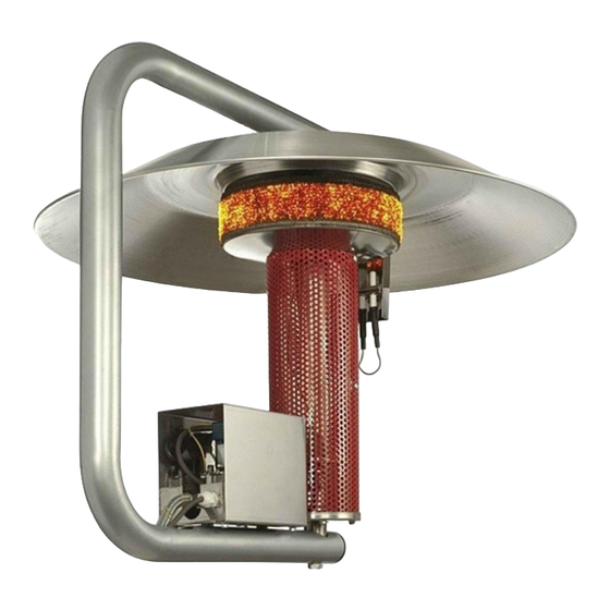
- Page 1 Infra-red Gas Heaters MANUAL for INSTALLATION, RUNNING and MAINTENANCE Models: UFO EB /08 and UFO M /08 Version “UFO /08” SIABS S.r.l. – ITALY Phone +39 02 90384081 E-mail commerciale@siabs.it via Del Lavoro, 7 +39 02 9029538 Web site www.siabs.com...
-
Page 2: Table Of Contents
For Your safety Warranty terms Labels . plate with technical data . packing label Technical data . appliances version UFO EB/08 (electronic start-up, two-stages) . appliances version UFO M/08 (manual start-up, on-off) Installation 7 to 15 . ventilation . positioning . -
Page 3: General Instruction
GENERAL INSTRUCTIONS for INSTALLER, USER and MAINTENANCE PERSONNEL Thank you for your preference and trust granted! SIABS is pleased to have You among his Customers; our appliances are designed and manufactured to the most modern and rational processing systems and we do think that their use will be fully satisfactory. -
Page 4: For Your Safety
Warranty SIABS guarantees its products, whether installed by authorized personnel, for a period of 24 months from the invoice date. The warranty does not cover the components supplied by third parties, these are subject to the conditions of the original warranty. -
Page 5: Labels
Plate label On each unit you will find a plate with technical data – do not remove – placed on the cover of the gas group. Apparatus type A1, gas category II 2H3P Plate label (f.e.: appliance UFO E B/08, electronic start-up, version two-stages, G20 gas) Essential features of the appliance are given on the packing label, outside on the packing box. -
Page 6: Technical Data
TECHNICAL DATA Appliance model UFO EB /08 UFO M /08 Electric feeding 230 Volt - 1phase - 50 Hz MAX feeding pressure (mbar) 50,0 50,0 Gas group Gas connection 1 x 3/8" 1 x 3/8" Absorbed power (Watt) NOx class Weight (kg) Cover diameter... -
Page 7: Installation
INSTALLATION Ventilation of the ambient Appliances must installed well- ventilated manned ambient, compliance with current legislation The unit leaves the combustion products into the environment in which it is used (appliance type A1). It is therefore necessary to ensure ventilation and air changes of the premises in which the appliance is installed, realizing appropriate air outlet openings on the perimeter walls of the same, or creating a system of mechanical ventilation. -
Page 8: Positioning
Positioning The appliance must be installed / suspended at ceiling (Picture 1). On top of the tube structure is welded a plate (Picture 2) drilled to balance the weight of the appliance. On request, S hooks and chains can be provided for hanging installation. Picture 1 IMPORTANT: appliances must be installed in vertical position Handling... -
Page 9: Minimum Height Of Installation (For People Comfort)
MINIMUM height of installation (for people comfort) Indicative heights for the installation of appliances are as follows: MODEL HEIGHT of INSTALLATION (mt) UFO EB / 08 (electronic start-up, TWO-STAGES version) UFO M / 08 (manual start-up, ON-OFF version) Height “MIN" means the minimum height at which the appliance should be installed so that people who are in radiated zone, are not subject to excessive heat. -
Page 10: Assembling
ASSEMBLING Open the packing box and take out the appliance (Picture 1) and the aluminium cover (Picture Picture 1 Picture 2 Remove the nut and washer from the M8 pin, fixed on the upper part of the burner (Picture 3). Picture 3 Place the cover (Picture 4);... -
Page 11: Connection To Gas Supply
Connection to GAS supply IMPORTANT: hydraulic connection of the appliances to the gas distribution net must be made according to information given in this technical book exclusively by professionally qualified staff. The appliances are supplied according to the type of gas chosen, and then before making the connection to the power network of gas, make sure that the gas used and pressure of gas circuit correspond to what is shown on the data plate label of the unit. -
Page 12: Connection To Electric Feeding
Connection to ELECTRIC feeding (for appliance UFO EB /08 with electronic start-up) IMPORTANT: the electrical connection of the equipment shall be made in accordance with the directions given in this technical book exclusively by professionally qualified personnel. The installation must be carried out in accordance with regulations in the country of installation. - Page 13 NOTE for “SIT” TWO-STAGE gas valve IMPORTANT: for this version, a specific switch for pressure modulator feeding must be placed in the main electric switchboard modulator fed: HIGH pressure running modulator NOT fed: LOW pressure running start-up of the appliance must always take place with the modulator fed (HIGH pressure running) you will find the data (heat input, pressure and gas flow rate) referring to the appliances with TWO-STAGE version, in the tables at page 6 of this manual.
-
Page 14: Sit Control Unit, Two-Stage Version 13 And
Setting of the pressure Unscrew the screw of the PO pressure intake of the gas valve before the nozzle (pictures 1.A and 1.B), and connect a water column manometer. Feed the modulator and take out the yellow tap of the pressure regulator. Act, as shown in picture 2, on the CH10 screw for setting of the maximum pressure, till you get the required pressure (turn clockwise to increase and counter clockwise to decrease). -
Page 15: Sit Control Unit, Wiring Diagram, Two-Stage Version
WIRING DIAGRAM, “SIT” control unit TWO-STAGE pag. 15 Manu_ENG_UFO_ rev. 0_04_2012... -
Page 16: Put In Operation And First Start-Up 16 To
PUT IN OPERATION and FIRST START-UP (for all the models) When you first start the appliances is important to make some preliminary checks to ensure its proper running; operations listed below are considered essential: make sure there are no losses in the gas line and that is properly sized ... - Page 17 IMPORTANT: in case of failure at time of first start-up, pressure settings have to be checked, acting on pressure intakes Only in case of maintenance, following instruction of qualified SIABS personnel, pressure settings can be modified using the following procedure: ...
-
Page 18: Appliances Version Ufo Eb/08 (Electronic Start-Up, Two-Stages) 17 And
remove the cap of pressure regulator (Picture 3) and act on the screw of adjustment (Picture 4) till match up to the pressure gauge reading with that stated on plate label (turn clockwise to increase and counter clockwise to decrease). Picture 3 Picture 4 ... -
Page 19: Appliances Version Ufo M/08 (Manual Start-Up, On-Off)
IMPORTANT: in case of failure at time of first start-up, pressure settings have to be checked, acting on pressure intakes Only in case of maintenance, following instruction of qualified SIABS personnel, pressure settings can be modified using the following procedure: ... -
Page 20: Ordinary Maintenance (Suggestions)
For all routine and / or extraordinary maintenance, contact only professionally qualified staff, or rather a Technical Assistance Centre authorized by SIABS At least once a year before the season of use, it is strongly advisable to perform an intervention for control / inspection and cleaning: ... -
Page 21: Nozzle Replacement
In case you need to change the type of gas for which the appliance was prepared, you should contact SIABS to get the specific transformation kit, specifying the model of appliance, serial number and the new gas. The operations must be performed by qualified personnel and in compliance with the regulations. -
Page 22: Maintenance And Annual Check 20 To
Trouble shooting TROUBLE POSSIBLE CAUSE SOLUTION A the heater turns on, A1 Phase and Neutral with wrong A1 Check Phase / Neutral polarity the ignition electrode connection and eart connection continues to sparkle A2 The flame detection electrode is too far A2 Verify that the flame detection electrode is then goes to block from radiant superface... -
Page 23: Decommissioning And Disposal (Norms For User)
____ ____ Model with MANUAL start-up . SIT gas valve, model M1C – 3/8” M-M 2550000002 ____ . piezo starter, with wiring SIABS:A 1*0,75 PZ10026 ____ . thermo-couple 2552000021 ____ N.B. – specify appliance(s) model and gas type when ordering spare-parts Decommissioning and disposal INFORMATION TO USERS "Implementation of Directives 2002/95/EC, 2002/96/EC and... -
Page 24: Ce Certificate
CE certificate pag. 24 Manu_ENG_UFO_ rev. 0_04_2012... -
Page 25: Service Sheet
DATE and STAMP OPERATION / NOTES DATE and STAMP OPERATION / NOTES DATE and STAMP OPERATION / NOTES DATE and STAMP OPERATION / NOTES pag. 25 Manu_ENG_UFO_ rev. 0_04_2012... - Page 26 SIABS S.r.l. via Del Lavoro, 7 20010 – Casorezzo (MILAN) ITALY ___________________________________________________________________________ to contact us: Phone +39 02 90384081 +39 02 9029538 E-mail commerciale@siabs.it Web page www.siabs.com Continuous development to improve the product could cause changes of above without notice.
Need help?
Do you have a question about the UFO EB/08 and is the answer not in the manual?
Questions and answers