
Related Manuals for LEGO Excavator


Summary of Contents for LEGO Excavator
- Page 1 LEGO Excavator Teledyne PDS Version 1.0.0 June 2017 Teledyne RESON B.V. Stuttgartstraat 42- 44 3047 AS Rotterdam The Netherlands Tel.: +31 (0)10 245 15 00 www.teledyne-reson.com...
- Page 2 Teledyne RESON has made every effort to ensure the accuracy and completeness of this document; however, because ongoing development efforts are made to continually improve the capabilities of our products, we cannot guarantee the accuracy of the contents of this document. We disclaim liability for errors, omissions, or future changes herein.
-
Page 3: Table Of Contents
Contents 1 LEGO Excavator Introduction ...................... 1 2 LEGO Excavator preparations Introduction ...................... 3 The LEGO Excavator ..................3 Potentiometers ....................4 2.3.1 Boom ......................5 2.3.2 Stick ......................7 2.3.3 Bucket ......................9 2.3.4 Electrical connection ................12 2.3.5 Potentiometer range adjustment.............. -
Page 5: Lego Excavator
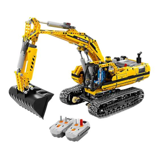
For demonstration and training purposes, Teledyne RESON has implemented her dredge monitoring system to a LEGO Excavator. The behavior of the excavator is visualized in Teledyne PDS and gives the user a real life experience of the Teledyne PDS Excavator application. -
Page 7: Lego Excavator Preparations
2 LEGO Excavator preparations 2.1 Introduction The following is needed to use the LEGO Excavator for the PDS Excavator application: LEGO Excavator Three 5k ohm potentiometers Teledyne RESON Dredge (LEGO) interface Teledyne PDS license Additional LEGO axis (to connect potentiometer to boom, stick and bucket). -
Page 8: Potentiometers
5K ohm linear Single turn with shaft Bucket 5K ohm linear Single turn with shaft The potentiometers are mounted on the crane. The wiring is connected to the Teledyne RESON LEGO interface. 4 LEGO Excavator preparations Teledyne PDS - LEGO Excavator... -
Page 9: Boom
Figure 2-4 Boom potentiometer location The potentiometer is fixed to the chassis. The axis of the potentiometer is fixed to a LEGO axis. The LEGO axis is fixed to the boom. LEGO Excavator preparations 5 Teledyne PDS - LEGO Excavator... - Page 10 Crane chassis Crane boom Thread of potentiometer fixed in chassis LEGO Axis fixed to potentiometer axis Potentiometer Axis fixed into boom Figure 2-5 Boom axis Figure 2-6 Axis fixed to boom. 6 LEGO Excavator preparations Teledyne PDS - LEGO Excavator...
-
Page 11: Stick
Figure 2-8 Stick potentiometer mounting The potentiometer is fixed to the boom. The axis of the potentiometer is fixed to a LEGO axis. The LEGO axis is fixed to the stick. LEGO Excavator preparations 7 Teledyne PDS - LEGO Excavator... - Page 12 Boom Thread of potentiometer fixed in boom Stick Axis fixed into Potentiometer stick Figure 2-9 Connection of axis Figure 2-10 Axis fixed to stick 8 LEGO Excavator preparations Teledyne PDS - LEGO Excavator...
-
Page 13: Bucket
The bucket potentiometer is placed on the left side of the crane. Figure 2-11 Bucket potentiometer location The bucket potentiometer is connected to a parallelogram. The parallelogram is made from other or spare LEGO blocks. Figure 2-12 Potentiometer connected to support lever LEGO Excavator preparations 9... - Page 14 Figure 2-14 Drawing potentiometer connecter to parallelogram arm The parallelogram (red colored blocks) is connected to the support lever (yellow colored block). Support lever Parallelogram Stick Figure 2-15 Parallelogram 10 LEGO Excavator preparations Teledyne PDS - LEGO Excavator...
- Page 15 Figure 2-16 Parallelogram on crane LEGO Excavator preparations 11 Teledyne PDS - LEGO Excavator...
-
Page 16: Electrical Connection
2.3.4 Electrical connection The potentiometers are connected to the Teledyne RESON (LEGO) interface. The potentiometer are connected to 20VDC and to ground of the Wago 857-414 terminal and the potentiometer slider to the Wago 857-414 ‘In+’ terminal. See the following connection diagram. -
Page 17: Potentiometer Range Adjustment
1. Set the boom, stick and bucket in the center position. Figure 2-17 Boom, stick and bucket in center position 2. Adjust the potentiometers to output 5VDC by turning the potentiometer slider. 20VDC 5VDC Figure 2-18 Potentiometer position adjusted LEGO Excavator preparations 13 Teledyne PDS - LEGO Excavator... -
Page 19: Drivers & Crane Configuration
3 Drivers & Crane configuration 3.1 Introduction Setup a PDS excavator project. See the Teledyne PDS Excavator User and the PDS Excavator User manuals for more information about an excavator PDS project. (Contact the Sales department of Teledyne RESON Rotterdam for a LEGO Crane demonstration project.) -
Page 20: Driver Properties
See also the next figure. Set the: 1. Device offset. Boom pin location. For the Hitachi Lego crane this is set to X:0; Y:1.0; Z:1.0 The boom, stick and tools are configured in the Crane Configuration of the Vessel Configuration’s Tools page. -
Page 21: Crane Configuration
2. It is possible to select a custom shape or a standard shape. The standard shape is resized automatically to the entered boom parameters. Figure 3-3 Crane configuration - Boom Drivers & Crane configuration 17 Teledyne PDS - LEGO Excavator... -
Page 22: Stick
4. The effective area width is set to 0.85. 5. It is possible to select a custom shape or a standard shape. The standard shape is resized automatically to the entered stick parameters. 18 Drivers & Crane configuration Teledyne PDS - LEGO Excavator... - Page 23 Figure 3-5 Crane configuration - Tool Drivers & Crane configuration 19 Teledyne PDS - LEGO Excavator...
- Page 25 Positioning device - 16 potentiometers - 4, 12 ─ R ─ range - 13 ─ S ─ stick potentiometer - 7 ─ V ─ VRU - 16 ─ W ─ Wago 857-414 - 12 Index 21 Teledyne PDS - LEGO Excavator...
Need help?
Do you have a question about the Excavator and is the answer not in the manual?
Questions and answers