
Subscribe to Our Youtube Channel
Related Manuals for TE Connectivity FlexWave Prism


Summary of Contents for TE Connectivity FlexWave Prism
- Page 1 ® FlexWave Prism RF Modules for Prism Remote Units Installation Guide TECP-77-141 Issue 5 November 2013 Single-Slot RF Module Dual-Band Dual-Slot RF Module HDM RF Module Dual-Slot 40W RF Module 300001744178 Rev E...
- Page 2 © 2013 TE Connectivity, Inc. All Rights Reserved. Information contained in this document is company private to TE Connectivity Ltd., and shall not be modified, used, copied, reproduced or disclosed in whole or in part without the written consent of TE.
-
Page 3: Table Of Contents
Connect the RF Module Cables ..........................37 Connecting Cables in a Single‐Slot RF Module Installation ....................38 Connecting Cables in a Dual‐Slot RF Module Installation....................40 Power on the RF Module............................45 Contacting TE Connectivity ..........................46 Contacting TE Connectivity by Telephone......................46 Contacting TE Connectivity Online ........................46 FlexWave Prism RF Modules for Prism Remote Units Installation Guide Page 1 TECP-77-141 Issue 5 • 300001744178 Rev E • November 2013 ©2013 TE Connectivity Ltd. -
Page 4: Preface
Specifications section, which included the RF and Optical Specifications and the Frequency and Composite Output Power at Antenna Port (dBm) for Prism Remote Units tables; to access these performance specifications, refer to the FlexWave Prism Performance Specifications (TECP-77-201); updated “Contacting TE Connectivity” on page... -
Page 5: Flexwave Prism User Documentation
Coarse Wavelength Division Multiplexer User Guide TECP-77-209 Release 8.1 is the earliest release of the FlexWave Prism EMS that supports the hardware features described in this installation guide. Release 8.1.1 is the earliest release of the FlexWave Prism EMS that supports the RF Modules added to this installation guide;... -
Page 6: Accessing User Documentation On The Te Customer Portal
On the Wireless Customer Portal home page in the panel, click the Manuals and Knowledge Center Data Sheets link. On the Manuals and Data Sheets page, do the following: In the panel, scroll to the section for the product line of the document Document Repository that you want to access. Click on the title of the manual that you wish to open. (Optional) Save the PDF to your PC or laptop. Page 4 FlexWave Prism RF Modules for Prism Remote Units Installation Guide © 2013 TE Connectivity Ltd TECP-77-141 Issue 5 • 300001744178 Rev E • November 2013... -
Page 7: Standards Certification
2006/95/EC, but with no voltage limit applying. Article 3.1b—The protection requirements with respect to electromagnetic compatibility • contained in Directive 2004/108/EC. Article 3.2—In addition, radio equipment shall be so constructed that it effectively uses • the spectrum allocated to terrestrial/space radio communication and orbital resources so as to avoid harmful interference. EMC Standards: EN 55022 and EN55024 (CE marked) Safety Standards: This equipment complies with IEC 60950‐1, 2ND Edition + Amendment 1 (CE marked) and with UL 60950‐1, 2ND Edition + Amendment 1 (File number E174166) (USA and Canada) FlexWave Prism RF Modules for Prism Remote Units Installation Guide Page 5 TECP-77-141 Issue 5 • 300001744178 Rev E • November 2013 © 2013 TE Connectivity Ltd. -
Page 8: Overview Of Rf Modules For Prus
The function of the PRU RF Modules on the Forward Path is to: convert the digitized RF transported from the Host to Analog RF • amplify the Analog RF signal • provide signal filtering. • The function of the PRU RF Modules on the Reverse Path is to: convert the Analog RF from the handset to Digital RF for transport to the Host • provide signal filtering. • Page 6 FlexWave Prism RF Modules for Prism Remote Units Installation Guide © 2013 TE Connectivity Ltd TECP-77-141 Issue 5 • 300001744178 Rev E • November 2013... -
Page 9: Pru Rf Module Types
HDM‐700 has two sets. – Each RF Module will have up to two 6‐timeslot DARTs or one 12‐timeslot DARTs per RF Module. The RF Modules are field replaceable, but cannot be serviced in the field. PRU RF Module Types The PRU RF Modules are available in the following formats, and as described in the following sections: “Prism Remote Unit Single‐ and Dual‐Card RF Modules” on page 8 • “Prism Remote Unit HDM RF Modules” on page 9 • “Prism Remote Unit Dual‐Slot 40W RF Modules” on page 10. • FlexWave Prism RF Modules for Prism Remote Units Installation Guide Page 7 TECP-77-141 Issue 5 • 300001744178 Rev E • November 2013 © 2013 TE Connectivity Ltd. -
Page 10: Prism Remote Unit Single- And Dual-Card Rf Modules
Single-Slot Dual-Card RF Module Dual-Band Dual-Slot RF Module Single- and Dual-Slot RF Modules Figure 2. Page 8 FlexWave Prism RF Modules for Prism Remote Units Installation Guide © 2013 TE Connectivity Ltd TECP-77-141 Issue 5 • 300001744178 Rev E • November 2013... -
Page 11: Prism Remote Unit Hdm Rf Modules
MIMO/Dual Band Module (1) 850 20W and 40W only. (2) 700 MIMO 20W and 850/1900 20W only. FlexWave Prism RF Modules for Prism Remote Units Installation Guide Page 9 TECP-77-141 Issue 5 • 300001744178 Rev E • November 2013 © 2013 TE Connectivity Ltd. -
Page 12: Prism Remote Unit Dual-Slot 40W Rf Modules
20W, GSM 1800, NON-DIVERSITY, DL SD FWP-7 4260 00M OD 20W, GSM 1800, DIVERSITY, SGL SD Page 10 FlexWave Prism RF Modules for Prism Remote Units Installation Guide © 2013 TE Connectivity Ltd TECP-77-141 Issue 5 • 300001744178 Rev E • November 2013... - Page 13 DUAL 20W 700 UPPER C MODULE, MIMO FWP-U81 6100 MOD 40W 700 Upper C MODULE, NON-DIVERSITY, SGL SD (SGL-SLOT) FlexWave Prism RF Modules for Prism Remote Units Installation Guide Page 11 TECP-77-141 Issue 5 • 300001744178 Rev E • November 2013...
-
Page 14: Rf Module Components
Tx and Rx Cards Duplexers Power Amplifier Mounting hook Mounting latch HDM RF Module Components Figure 6. Page 12 FlexWave Prism RF Modules for Prism Remote Units Installation Guide © 2013 TE Connectivity Ltd TECP-77-141 Issue 5 • 300001744178 Rev E • November 2013... -
Page 15: Duplexer And Low Noise Amplifier
LTE 700 Upper C PCS 1900 PGSM 900 SMR 800 SMR 900 UMTS 2100 15.8 FlexWave Prism RF Modules for Prism Remote Units Installation Guide Page 13 TECP-77-141 Issue 5 • 300001744178 Rev E • November 2013 © 2013 TE Connectivity Ltd. -
Page 16: Digital Processing Module
NOTE: Industry Canada 20 dB Pass Band Model Number FWP‐C4MT000MOD Cellular 850 MHz = 26.3 MHz and the PCS 1900 = 66.8 MHz. Digital Processing Module The Digital Processing Module (DPM) is found only in the HDM RF Modules. The DPM provides the primary processing and logic functions for the HDM RF Module. It also provides the primary power interface for the HDM RF Module, and conversion of the native 28 Vdc voltage to lower voltages as necessary for functionality. The DPM has a Transmit (Tx) Board and a Receive (Rx) Board: Tx Board—provides band specific filtering for the intended Transmit path. • Rx Board—provides band specific filtering for the intended Receive path. • Page 14 FlexWave Prism RF Modules for Prism Remote Units Installation Guide © 2013 TE Connectivity Ltd TECP-77-141 Issue 5 • 300001744178 Rev E • November 2013... -
Page 17: Understanding The Rf Module Cables
Align and fully insert the LVDS cable connectors into their respective connector cages. Full • insertion is identified by an audible click. Ensure the two LVDS cables are fully seated and latched into their respective receptacles on • the RF Module by lightly pulling outward on the connectors. If fully seated and locked into position, the cable connectors will not slide back out. Maintain adequate strain‐relief distances from the connection points to the RF Module. • RF Cable Connections The RF Module cables that are pre‐installed in the PRU connect to the corresponding connectors on the RF Module. The RF Module cables correlate to the antenna connectors on the bottom of the PRU chassis. FlexWave Prism RF Modules for Prism Remote Units Installation Guide Page 15 TECP-77-141 Issue 5 • 300001744178 Rev E • November 2013 © 2013 TE Connectivity Ltd. -
Page 18: Rf Cable Rules
Diversity receive for RF power from the TX1/RX1 antenna for RF Module A Page 16 FlexWave Prism RF Modules for Prism Remote Units Installation Guide © 2013 TE Connectivity Ltd TECP-77-141 Issue 5 • 300001744178 Rev E • November 2013... -
Page 19: Rf Module Cables For Dual-Slot Installations
RF Modules are present, install the 2100 Module in the lower-most slot and the 1900 Module in the upper-most slot. FlexWave Prism RF Modules for Prism Remote Units Installation Guide Page 17 TECP-77-141 Issue 5 • 300001744178 Rev E • November 2013... -
Page 20: Rf Group Assignments For Prus
SeRF Module DART RF Groups in a Prism Remote Unit (PRU) Figure 7. Page 18 FlexWave Prism RF Modules for Prism Remote Units Installation Guide © 2013 TE Connectivity Ltd TECP-77-141 Issue 5 • 300001744178 Rev E • November 2013... - Page 21 RF Group Assignments for PRUs Table 9 lists how the FlexWave Prism EMS references the RF group assignments and corresponding components of each RF Module. Table 9. Remote Unit RF Group Assignments (from Top/Down) LNA Number Power Power Detector Detector...
- Page 22 To accommodate two‐slot modules, you need to remove a module slot shelf as described in “Dual‐Slot Modules Only—Remove the Module Slot Shelf” on page 25. Page 20 FlexWave Prism RF Modules for Prism Remote Units Installation Guide © 2013 TE Connectivity Ltd TECP-77-141 Issue 5 • 300001744178 Rev E • November 2013...
-
Page 23: Safety Precautions
CAUTION! This system is an RF Transmitter and continuously emits RF energy. Maintain 3 foot (91.4 cm) minimum clearance from the antenna while the system is operating. Wherever possible, shut down the RAN before servicing the antenna. FlexWave Prism RF Modules for Prism Remote Units Installation Guide Page 21 TECP-77-141 Issue 5 • 300001744178 Rev E • November 2013 © 2013 TE Connectivity Ltd. -
Page 24: Install The Rf Module(S)
Handle the RF Module with care during installation. Be especially careful to not damage the thermal‐interface material (TIM), which is attached to the LPA. If the TIM is damaged, the LPA can overheat. Before installing the RF Module, check to see if the heatsink material is gouged or cracked. If the TIM is damaged, do not install the RF Module and contact TE Connectivity for assistance (see “Contacting TE Connectivity” on page 46 for contact information). CAUTION! If the thermal‐interface material is damaged, the installation and use of the RF Module may void the warranty of the RF Module. Page 22 FlexWave Prism RF Modules for Prism Remote Units Installation Guide © 2013 TE Connectivity Ltd TECP-77-141 Issue 5 • 300001744178 Rev E • November 2013... -
Page 25: Remove Release Liners From The Rf Module
(bottom of the LPA) Thermal Pads on a Dual-Slot 40W RF Module Figure 9. FlexWave Prism RF Modules for Prism Remote Units Installation Guide Page 23 TECP-77-141 Issue 5 • 300001744178 Rev E • November 2013 © 2013 TE Connectivity Ltd. - Page 26 NOTE: Tx and Rx cards are paired: Tx A ony pairs with Rx A and Tx B only pairs with Rx B. Thermal Pads on an HDM RF Module Figure 10. Page 24 FlexWave Prism RF Modules for Prism Remote Units Installation Guide © 2013 TE Connectivity Ltd TECP-77-141 Issue 5 • 300001744178 Rev E • November 2013...
-
Page 27: Dual-Slot Modules Only-Remove The Module Slot Shelf
Remove Module B Shelf for Dual-Slot 40W RF Modules in the following graphic. Discard or store the module shelf and fasteners. FlexWave Prism RF Modules for Prism Remote Units Installation Guide Page 25 TECP-77-141 Issue 5 • 300001744178 Rev E • November 2013 © 2013 TE Connectivity Ltd. -
Page 28: Install The Rf Module Into The Prism Remote Chassis
NOTE: Always install RF Modules from the bottom up. Do not skip a slot. Holding the RF Module at a 45° angle in respect to the rear heatsink, rest the bottom surface of the module on the RF Module shelf, as shown in one of the following graphics, and as applicable to the RF Module. Single‐Slot RF Module: Figure 11 on page 27 • HDM RF Module: Figure 12 on page 28 • Dual‐Bay Dual‐Slot RF Module: Figure 13 on Page 29 • Dual‐Slot 40W RF Module: Figure 14 on Page 30. • Page 26 FlexWave Prism RF Modules for Prism Remote Units Installation Guide © 2013 TE Connectivity Ltd TECP-77-141 Issue 5 • 300001744178 Rev E • November 2013... - Page 29 RF MOD B RF MOD A SeRF Module Installing a Single-Slot RF Module Figure 11. FlexWave Prism RF Modules for Prism Remote Units Installation Guide Page 27 TECP-77-141 Issue 5 • 300001744178 Rev E • November 2013 © 2013 TE Connectivity Ltd.
- Page 30 RF MOD B RF MOD A SeRF Module Installing an HDM RF Module Figure 12. Page 28 FlexWave Prism RF Modules for Prism Remote Units Installation Guide © 2013 TE Connectivity Ltd TECP-77-141 Issue 5 • 300001744178 Rev E • November 2013...
- Page 31 Installing a Dual-Band Dual-Slot RF Module Installing a Dual-Bay Dual-Slot RF Module Figure 13. FlexWave Prism RF Modules for Prism Remote Units Installation Guide Page 29 TECP-77-141 Issue 5 • 300001744178 Rev E • November 2013 © 2013 TE Connectivity Ltd.
- Page 32 Install the RF Module(s) Installing a Dual-Slot 40W RF Module Figure 14. Page 30 FlexWave Prism RF Modules for Prism Remote Units Installation Guide © 2013 TE Connectivity Ltd TECP-77-141 Issue 5 • 300001744178 Rev E • November 2013...
- Page 33 Install the RF Module into the Prism Remote Chassis Align the Mounting Hook on the module with the receiving flange on the PRU heat sink, and then slide the RF Module in toward the flange until it can go no further. RF Module Mounting hook Chassis Receiving flange FlexWave Prism RF Modules for Prism Remote Units Installation Guide Page 31 TECP-77-141 Issue 5 • 300001744178 Rev E • November 2013 © 2013 TE Connectivity Ltd.
- Page 34 Seating a Single-Slot RF Module Figure 15. Page 32 FlexWave Prism RF Modules for Prism Remote Units Installation Guide © 2013 TE Connectivity Ltd TECP-77-141 Issue 5 • 300001744178 Rev E • November 2013...
- Page 35 RF Module Seating an HDM RF Module Figure 16. FlexWave Prism RF Modules for Prism Remote Units Installation Guide Page 33 TECP-77-141 Issue 5 • 300001744178 Rev E • November 2013 © 2013 TE Connectivity Ltd.
-
Page 36: Secure Rf Module Latches
Seating a Dual-Slot RF Module Figure 17. Secure RF Module Latches To secure the module latches on the left side of the RF Module, do one of the following, as appropriate for the RF Module being installed: “Connect Latches on Single‐Slot and HDM RF Modules” on page 35 • “Connect Latches on Dual‐Bay Dual‐Slot RF Modules” on page 36. • Page 34 FlexWave Prism RF Modules for Prism Remote Units Installation Guide © 2013 TE Connectivity Ltd TECP-77-141 Issue 5 • 300001744178 Rev E • November 2013... -
Page 37: Connect Latches On Single-Slot And Hdm Rf Modules
Two latches on HDM RF Modules Latches on Single-Slot and HDM RF Modules Figure 18. FlexWave Prism RF Modules for Prism Remote Units Installation Guide Page 35 TECP-77-141 Issue 5 • 300001744178 Rev E • November 2013 © 2013 TE Connectivity Ltd. -
Page 38: Connect Latches On Dual-Bay Dual-Slot Rf Modules
Four latches in a Dual-Band Dual-Slot RF Module Dual-Bay Dual-Slot RF Module Latches Figure 19. Page 36 FlexWave Prism RF Modules for Prism Remote Units Installation Guide © 2013 TE Connectivity Ltd TECP-77-141 Issue 5 • 300001744178 Rev E • November 2013... -
Page 39: Latches On Dual-Slot 40W Rf Modules
Figure 20. Verify that the RF Module Mounting Hook is Engaged Verify that the RF Module Mounting Hook is engaged correctly by pulling the module away from the heat sink. The RF Module should not move. If the RF Module moves during this check, repeat all the steps starting at “Install the RF Module into the Prism Remote Chassis” on page 26 through this step. Connect the RF Module Cables The steps to connect the RF Module cables have been separated into two different procedures; follow the steps that correspond to the RF Module being installed. “Connecting Cables in a Single‐Slot RF Module Installation” on page 38 • “Connecting Cables in a Dual‐Slot RF Module Installation” on page 40. • FlexWave Prism RF Modules for Prism Remote Units Installation Guide Page 37 TECP-77-141 Issue 5 • 300001744178 Rev E • November 2013 © 2013 TE Connectivity Ltd. -
Page 40: Connecting Cables In A Single-Slot Rf Module Installation
Module Receptacle. This can be verified by lightly pulling back on the LVDS connector while making sure not to depress the release trigger. When fully inserted, the cable should not be able to be removed from the receptacle. Connect the Power Cable Connector to the PWR receptacle of the RF Module by inserting and sliding in until fully seated. NOTE: Full insertion can be recognized by an audible click as the Power Cable Connector locks into the RF Module Receptacle. This can be verified by lightly pulling back on the Power Cable Connector while making sure not to depress the release triggers on the ends of the connector. When fully inserted, the cable should not be able to be removed from the receptacle. Page 38 FlexWave Prism RF Modules for Prism Remote Units Installation Guide © 2013 TE Connectivity Ltd TECP-77-141 Issue 5 • 300001744178 Rev E • November 2013... - Page 41 Edge of Connector Interface Panel Cable Connections for Single-Slot RF Modules Figure 21. CAUTION! Ensure that all cable bends are below the top edge of the Connector Interface Panel as indicated by the dashed line in the preceding figure. Failure to correctly position the cables could inhibit closing the PRU door, which can result in damage to the cables. FlexWave Prism RF Modules for Prism Remote Units Installation Guide Page 39 TECP-77-141 Issue 5 • 300001744178 Rev E • November 2013 © 2013 TE Connectivity Ltd.
-
Page 42: Connecting Cables In A Dual-Slot Rf Module Installation
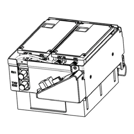
The upper RF Module shelf will either not be present (factory installed module) or will be • removed prior to installation (field installed module). The MOD N TX0/RX0 cable for the lower RF Module slot will need to be connected to the • MOD N TX0/RX0 N‐Style RF connection of the Dual‐Slot RF Module. Constrain the MOD N TX1/RX1 cable to the existing cables using a tie wrap such so it • cannot be pinched or prevent the PRU door from closing. Do not cut or attempt to otherwise remove this RF cable. The Power (PWR) cable and two LVDS cables of the upper RF Module slot are not used • when installing a Dual‐Slot RF Module. Page 40 FlexWave Prism RF Modules for Prism Remote Units Installation Guide © 2013 TE Connectivity Ltd TECP-77-141 Issue 5 • 300001744178 Rev E • November 2013... - Page 43 Module connection is not available, constrain the MOD N TX0/RX0 cable to accompanying cables using a tie wrap so it cannot be pinched or prevent the PRU door from closing. Turn the coupling nut of the plug clockwise to thread onto the jack and finger‐tighten. Torque coupling nut to 8 +/‐ 1 in‐lbs to ensure full connection. NOTE: Insufficient torque applied to RF Module connections can result in elevated insertion/return loss and higher than normal VSWR reported by the system. FlexWave Prism RF Modules for Prism Remote Units Installation Guide Page 41 TECP-77-141 Issue 5 • 300001744178 Rev E • November 2013 © 2013 TE Connectivity Ltd.
- Page 44 Module by inserting and sliding in until fully seated. If PWR receptacle is not available, constrain the Power Cable to accompanying cables using a tie wrap so it cannot be pinched or prevent the PRU door from closing. NOTE: Full insertion can be recognized by an audible click as the Power Cable Connector locks into the RF Module Receptacle. This can be verified by lightly pulling back on the Power Cable Connector while making sure not to depress the release triggers on the ends of the connector. When fully inserted, the cable should not be able to be removed from the receptacle. Refer to the graphic that corresponds to the RF Module being installed in a dual‐slot: Dual‐Bay Dual‐Slot RF Module: Figure 23 on Page 43 • Dual‐Slot 40W RF Module: Figure 24 on Page 44. • Page 42 FlexWave Prism RF Modules for Prism Remote Units Installation Guide © 2013 TE Connectivity Ltd TECP-77-141 Issue 5 • 300001744178 Rev E • November 2013...
- Page 45 RX1 cable N-Type RF connector Cable Connections for Dual-Bay Dual-Slot RF Modules Figure 23. FlexWave Prism RF Modules for Prism Remote Units Installation Guide Page 43 TECP-77-141 Issue 5 • 300001744178 Rev E • November 2013 © 2013 TE Connectivity Ltd.
- Page 46 RX1 cable Cable Connections for Dual-Slot 40W RF Modules Figure 24. CAUTION! Ensure that all cable bends are below the top edge of the Connector Interface Panel as indicated by the dashed line in the preceding figure. Failure to correctly position the cables could inhibit closing the PRU door, which can result in damage to the cables. Page 44 FlexWave Prism RF Modules for Prism Remote Units Installation Guide © 2013 TE Connectivity Ltd TECP-77-141 Issue 5 • 300001744178 Rev E • November 2013...
-
Page 47: Power On The Rf Module
DC Power switch for Mod B switch for DC Power switch for Mod A Remote chassis Repeat all the steps in “Install the RF Module(s)” on page 21 to install other RF Modules. FlexWave Prism RF Modules for Prism Remote Units Installation Guide Page 45 TECP-77-141 Issue 5 • 300001744178 Rev E • November 2013 © 2013 TE Connectivity Ltd. -
Page 48: Contacting Te Connectivity
+1-952-917-0761 Contacting TE Connectivity Online Click on one of the following URLs, or past the URL into your web browser. Customer Portal https://www.te.com/portal/wireless/ Technical Support for Wireless Products http://www.te.com/WirelessSupport Page 46 FlexWave Prism RF Modules for Prism Remote Units Installation Guide © 2013 TE Connectivity Ltd TECP-77-141 Issue 5 • 300001744178 Rev E • November 2013... - Page 50 www.te.com/wireless...
Need help?
Do you have a question about the FlexWave Prism and is the answer not in the manual?
Questions and answers