Allen-Bradley E200 User Manual
Electronic overload relay/parameter configuration module
Hide thumbs
Also See for E200:
- Installation instructions (4 pages) ,
- Installation instructions (2 pages) ,
- Installation instructions and operators manual (2 pages)

Related Manuals for Allen-Bradley E200


Summary of Contents for Allen-Bradley E200
- Page 1 User Manual Original Instructions E200 Electronic Overload Relay/Parameter Configuration Module Bulletin Numbers 193, 592...
-
Page 2: Important User Information
Important User Information Read this document and the documents listed in the additional resources section about installation, configuration, and operation of this equipment before you install, configure, operate, or maintain this product. Users are required to familiarize themselves with installation and wiring instructions in addition to requirements of all applicable codes, laws, and standards. -
Page 3: Table Of Contents
Table of Contents Important User Information ........2 Preface Access Relay Parameters . - Page 4 Table of Contents Linear List Navigation ........24 System Info .
- Page 5 Table of Contents Non-reversing Starter (Operator Station) with Feedback ..58 Non-reversing Starter (Local I/O) – Two-wire Control..59 Non-reversing Starter (Local I/O) – Two-wire Control with Feedback ......61 Non-reversing Starter (Local I/O) –...
- Page 6 Table of Contents Two-speed Starter (Network & Local I/O) – Three-wire Control........106 Monitor Operating Mode.
- Page 7 Table of Contents Test Mode Trip ......... . 136 Analog Protection .
- Page 8 Wiring Diagrams E200 Wiring Configurations ........179 Index Index.
-
Page 9: Preface
Access Relay Parameters The Microsoft Excel spreadsheet that is attached to this PDF file details the E200 parameters. To use a spreadsheet file, click the Attachments link and right-click and save the desired file. If the PDF file opens in a browser and you don't see the Attachments link download the PDF file and then reopen the file with the Adobe Acrobat Reader application. - Page 10 Preface Notes: Rockwell Automation Publication 193-UM017A-EN-P - April 2019...
-
Page 11: Overview
Chapter Overview The E200™ Electronic Overload Relay is the newest part of the E300™ product portfolio. This device is a Parameter Configuration module communication option that is targeted for non-networked (remote) electronic motor overload protection applications. The E200 overload relay is configurable using the Connected Components Workbench™... -
Page 12: Thermal Overload Features
Two-Speed Protection accomplished with one device. Current Monitoring Functions The E200 Electronic Overload Relay lets you monitor the following operational data over a communications network: • Individual phase currents — in amperes • Individual phase currents — as a percentage of motor FLA •... -
Page 13: Ground (Earth) Fault
Note: The E200 Electronic Overload Relay is not a Ground Fault Circuit Interrupter for personnel protection (or Class I) as defined in article 100 of the U.S. National Electric Code. -
Page 14: Sensing Module Features
• Three rotary dials to set Full Load Amps (FLA) • 8-position DIP switch for trip class and feature selection Expansion Digital I/O You can add up to four additional expansion digital modules to the E200 relay expansion bus. • 4 inputs/2 relay outputs • 24V DC •... -
Page 15: Expansion Power Supply Features
• 24V DC Expansion Operator Station Features You can add one operator station to the E200 relay expansion bus to be used as a user interface device. The operator stations provide status indicators and function keys for motor control. The operator stations also support CopyCat™, which lets you upload and download configuration parameters. -
Page 16: Status Indicators
The Test/Reset button, which is located on the front of the E200 Electronic Overload Relay, lets you perform the following: • Test — The trip relay contact opens if the E200 Electronic Overload Relay is in an untripped condition and the Test/Reset button is pressed for 2 seconds or longer. -
Page 17: Diagnostic Information
• Trip Snapshot Simplified Wiring The E200 relay provides an easy means to mount to both IEC and NEMA Allen-Bradley® contactors. A contactor coil adapter is available for the 100-C contactor, which lets you create a functional motor starter with only two control wires. -
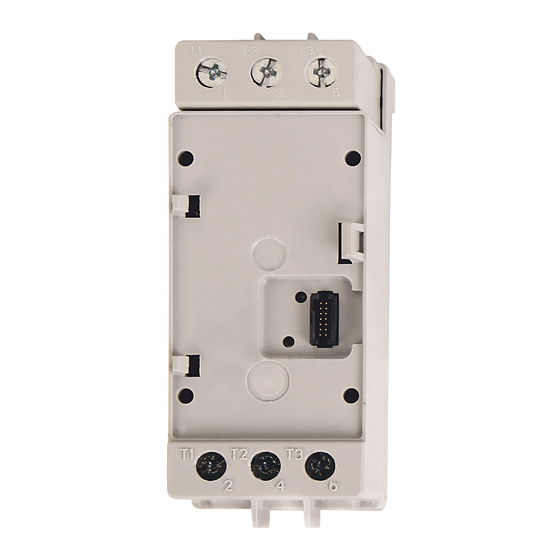
Page 18: Control Module
Control Module Figure 2 - Control Module The control module is the base of the E200 relay and can attach to any sensing module. The control module performs all protection and motor control algorithms and contains the native I/O for the system. The control module has two varieties: •... -
Page 19: Optional Add-On Modules
If the native I/O count of the base relay is not sufficient for your application, you can add more digital and analog I/O to the system via the E200 relay Expansion Bus. You can add any combination of up to four Digital I/O Expansion Modules that each have four inputs (120V AC, 240V AC, or 24V DC) and two relay outputs. -
Page 20: Optional Operator Station
Stop Reset The E200 relay lets you add one operator interface to the Expansion Bus. There are two types of operator stations: Control Station or a Diagnostic Station. Both types of operator stations mount into a standard 22 mm push button knockout, and they provide diagnostic status indicators that let you view the status of the E200 relay from the outside of an electrical enclosure. -
Page 21: Protection Features
• Overcurrent – load stall • Start Inhibit (66) Ground Fault Current-based Protection The E200 relay sensing modules and control modules with a ground fault current option provides the following motor protection function: • Ground Fault – zero sequence method (50 N) -
Page 22: Applications
Chapter 1 Overview Applications Use the E200 relay with the following across-the-line starter applications: • Non-reversing starter • Reversing starter • Wye (Star)/Delta starter • Two-speed motors • Low and medium voltage with two or three potential transformers • With or without Phase current transformers •... -
Page 23: Diagnostic Station
The E200 Diagnostic Station lets you view parameters by using a group menu system or by a linear list. To start the navigation menu, press the key. The menu prompts you to view parameters by groups, parameters in a linear list, or E200 relay system information. Parameter Group Navigation To start the navigation menu, press the key. -
Page 24: Linear List Navigation
Chapter 2 Diagnostic Station Use the keys to select the parameter group to display and press Use the keys to view the parameters that are associated with that group. When you view a bit-enumerated parameter, press to view the description of each bit. -
Page 25: System Info
The E200 Diagnostic Station can display firmware revision information, view the time and date of the E200 relay virtual clock, and edit the time and date of the E200 relay virtual clock. To view E200 relay system information, start the navigation menu by pressing key. -
Page 26: Editing Parameters
To start the navigation menu, press the key. You are prompted to view parameters by groups, parameters in a linear list, or E200 relay system information. Choose the appropriate method and navigate to the parameter to be modified. -
Page 27: Editing A Bit Enumerated Parameter
Programmable Display This section explains the programmable display sequence of the E200 relay. Sequence Display Sequence The Diagnostic Station of the E200 relay sequentially displays up to seven screens every 5 seconds. • Three-phase current • Three-phase voltage • Total power •... -
Page 28: Stopping The Display Sequence
436) defines, the Diagnostic Station automatically returns to the programmable display sequence. Automatic Trip and Warning When the E200 relay is in a trip or warning state, the E200 Diagnostic Station automatically displays the trip or warning event. Screens Press any of the navigation keys (... -
Page 29: System Operation And Configuration
Ready Mode Ready Mode is a standby mode for the E200 relay in which the relay is ready to help protect an electric motor and no electrical current has been detected. You can modify configuration parameters, update firmware, and issue commands if the appropriate security policies are enabled. -
Page 30: Option Match
Test Mode, it generates a Test Mode Trip. Invalid Configuration Mode Invalid Configuration Mode is an active mode for the E200 relay in which the relay is in a tripped state due to invalid configuration data. Invalid Configuration Parameter (Parameter 38) indicates the parameter number that is causing the fault. -
Page 31: Digital I/O Expansion Modules
Option Match feature for the communication module. Operator Station Type (Parameter 224) The E200 relay offers two different types of operator stations. Place the value of the expected operator station into Parameter 224. A value of (0) disables the Option Match feature for the operator station. -
Page 32: Analog I/O Expansion Modules
Digital Module 3 to the E200 relay system. Module 4 Type (Parameter 228) The E200 relay supports up to four additional Digital I/O expansion modules. This parameter configures the Option Match feature for the Digital I/O expansion module set to Digital Module 4. There are three different types of Digital I/O expansion modules. -
Page 33: Option Match Action (Parameter 233)
Device Reset • when this policy is disabled, all external reset message instructions return a communication error when the E200 relay is in Ready Mode or Run Mode • lets you update the internal firmware of the communication module and control module via ControlFlash when the E200 relay is in Ready Mode Firmware Update •... -
Page 34: Output Assignments
• Output Pt02 Assignment (Parameter 204) Output Relay Configuration When assigned as a Normal/General Purpose Relay or Control/Control & Trip Relay, you can configure the E200 relay's output relays to go to a specific safe state when one States of following events occur: •... -
Page 35: Output Relay Communication Fault Modes
If communication between the E200 relay and a network scanner or control system is not restored within the Fault Mode Output State Duration time (Parameter 561), the E200 output relays go to a final fault state (Open or Closed), which you configure by using the Final Fault Mode parameters. -
Page 36: Output Relay Communication Idle Modes
Parameter Fault Name Description • defines the amount of time (s) that the E200 relay remains in the Communication Fault Mode state when a communication fault occurs. 0 = forever Fault Mode Output State Duration • If communication between the E200 relay and a network scanner or control system is not... -
Page 37: Expansion Bus Fault
Mode or a PLC goes into Program Mode Expansion Bus Fault The expansion bus of the E200 relay can be used to expand the I/O capabilities of the device with the addition of digital and analog expansion I/O modules. The Expansion... -
Page 38: Emergency Start
IMPORTANT Activating Emergency Start inhibits overload and blocked start protection. Running in this mode can cause equipment overheating and fire. To enable the Emergency Start feature in the E200 relay, set the Emergency Start Enable (Parameter 216) to Enable. Table 7 - Emergency Start (Parameter 216) -
Page 39: Language
Description User-defined Screen 1 – Parameter 1 • the E200 parameter number to display for the first parameter in user-defined screen 1 User-defined Screen 1 – Parameter 2 • the E200 parameter number to display for the second parameter in user-defined screen 1 User-defined Screen 2 –... - Page 40 Chapter 3 System Operation and Configuration Table 10 - Universal Analog Input Signals Signal Type Possible Values Current 0…20 mA 4…20 mA Voltage 0…10V DC 1…5V DC 0…5V DC 2-Wire RTD Sensors 100 Ω, 200 Ω, 500 Ω, 1000 Ω 100 Ω, 200 Ω, 500 Ω, 1000 Ω...
- Page 41 System Operation and Configuration Chapter 3 Table 13 - Analog Input Data Format for RTD Input Type Engineering Engineering Raw / Input Range Input Value Condition Units Units x 10 Proportional 850.0 °C High Limit 8500 32767 16383 850.0 °C High Range 8500 32767...
-
Page 42: Analog Output Channel
Low Limit -32768 The performance for the input channels of the E200 Analog I/O Expansion Module is dependent on the filter setting for each channel. The total scan time for the input channels of the module is determined by adding the conversion time for all enabled input channels. - Page 43 Low Limit 0.00% The analog output can be used to communicate E200 diagnostic information via an analog signal to distributed control systems, programmable logic controllers, or panel- mounted analog meters. The analog output can represent one of the following E200 diagnostic parameters: •...
-
Page 44: Analog Modules
• defines the E200 relay parameter that Output Channel 00 represents Output Channel 00 Expansion Bus Fault Action • defines the value that Output Channel 00 provides when there is an E200 Expansion Bus fault Output Channel 00 Protection Fault Action •... - Page 45 • defines the value that the E200 Analog I/O Expansion Module Output Channel 00 provides when there is an E200 Output Channel 00 Expansion Bus Fault Action Expansion Bus fault • defines the value that the E200 Analog I/O Expansion Module Output Channel 00 provides when the E200 is in a Output Channel 00 Protection Fault Action tripped state (1) Open circuit detection is always enabled for this input channel.
- Page 46 • defines the value that the E200 Analog I/O Expansion Module Output Channel 00 provides when there is an E200 Output Channel 00 Expansion Bus Fault Action Expansion Bus fault • defines the value that the E200 Analog I/O Expansion Module Output Channel 00 provides when the E200 is in a Output Channel 00 Protection Fault Action tripped state (1) Open circuit detection is always enabled for this input channel.
-
Page 47: Introduction To Operating Modes
• defines the value that the E200 Analog I/O Expansion Module Output Channel 00 provides when there is an E200 Output Channel 00 Expansion Bus Fault Action Expansion Bus fault • defines the value that the E200 Analog I/O Expansion Module Output Channel 00 provides when the E200 is in a Output Channel 00 Protection Fault Action tripped state (1) Open circuit detection is always enabled for this input channel. - Page 48 Chapter 3 System Operation and Configuration Notes: Rockwell Automation Publication 193-UM017A-EN-P - April 2019...
-
Page 49: Operating Modes
You can also wire the E200 relay as a control relay so that the relay is controlled by local means and opens when a trip event occurs. -
Page 50: Overload (Network)
Motor (1) Contact shown with supply voltage applied. For Control Module firmware v3.000 and higher, you can also wire the E200 relay as a control relay so that the relay that is controlled by the communication network opens when a trip event occurs. -
Page 51: Overload (Operator Station)
The Overload (Operator Station) operating mode is used when an external source uses the start and stop keys of the E200 Operator Station for its motor control logic. Use commands locally or via external means to control the control relay or any of the remaining output relays that are assigned as normal output relays. -
Page 52: Overload (Local I/O)
E200 relay can use network commands to control the control relay or any of the remaining output relays that are assigned as Normal output relays. The reset button of the E200 Operator Station is disabled, and a digital input that is assigned as a trip reset is required. -
Page 53: Non-Reversing Starter Operating Modes
A normally open control relay controls the Operating Modes contactor coil. When a trip event occurs, the control relay remains open until the E200 receives a trip reset command. There are 15 non-reversing starter-based operating modes to choose from: •... -
Page 54: Non-Reversing Starter (Network) With Feedback
Input 0. If a feedback signal is not received before the time identified in Feedback Timeout (Parameter 213), the E200 Relay issues a trip or warning event. The reset button of the E200 Operator Station is enabled for this operating mode. Rockwell Automation Publication 193-UM017A-EN-P - April 2019... - Page 55 E200 Relay Relay 0 DeviceLogix Program The DeviceLogix program is automatically loaded and enabled in the E200 relay on power-up or when Operating Mode (Parameter 195) is set to a value of 4. Rockwell Automation Publication 193-UM017A-EN-P - April 2019...
-
Page 56: Non-Reversing Starter (Operator Station)
Operator Station’s “I” and “0” keys to control Relay 0, which controls the contactor coil. These keys are momentary push buttons, so the non-reversing starter remains energized when you release the “I” button. The E200 relay issues a trip or warning event if the E200 Operator Station disconnects from the base relay. -
Page 57: Rockwell Automation Publication 193-Um017A-En-P - April
I-Run 0-Stop DeviceLogix Program The DeviceLogix program is automatically loaded and enabled in the E200 relay on power-up or when Operating Mode (Parameter 195) is set to a value of 27. Timing Diagram Figure 14 - Non-reversing Starter (Operator Station) Timing Diagram... -
Page 58: Non-Reversing Starter (Operator Station) With Feedback
Non-reversing Starter (Operator Station) with Feedback Operating Mode Non-Reversing Starter (Operator Station) with Feedback (Parameter 195 = 28) uses the E200 Operator Station “I” and “0” keys to control Relay 0, which controls the contactor coil. These keys are momentary push buttons, so the non- reversing starter remains energized when you release the “I”... -
Page 59: Non-Reversing Starter (Local I/O) - Two-Wire Control
195 = 36) uses Input 0 to control Output Relay 0, which controls the contactor coil. Input 0 is a maintained value, so the non-reversing starter remains energized when Input 0 is active. The reset button of the E200 Operator Station is enabled for this operating mode. Rockwell Automation Publication 193-UM017A-EN-P - April 2019... - Page 60 Operating Modes IMPORTANT The Non-reversing Starter (Local I/O) – Two-wire Control operating mode uses the signal from Input 0 to control the starter. When an E200 relay powers up, the starter energizes if Input 0 is active. Rules 1. Output Pt00 Assignment (Parameter 202) must be set to Control Relay.
-
Page 61: Two-Wire Control With Feedback
The reset button of the E200 Operator Station is enabled for this operating mode. IMPORTANT The Non-reversing Starter (Local I/O) – Two-wire Control with Feedback operating mode uses the state of Input 1 to control the starter. When the E200 relay powers up, the starter energizes if Input 1 is active. Rules 1. -
Page 62: Non-Reversing Starter (Local I/O) - Three-Wire Control
Input 0 and Input 1 are momentary values, so the non-reversing starter only energizes if Input 0 is active and Input 1 is momentarily active. The reset button of the E200 Operator Station is enabled for this operating mode. Rockwell Automation Publication 193-UM017A-EN-P - April 2019... - Page 63 IN 1 Relay 0 DeviceLogix Program The DeviceLogix program is automatically loaded and enabled in the E200 relay on power-up or when Operating Mode (Parameter 195) is set to a value of 38. Timing Diagram Figure 22 - Non-reversing Starter (Local I/O) – Three-wire Control Timing Diagram...
-
Page 64: Non-Reversing Starter (Local I/O)
Feedback Timeout (Parameter 213), the E200 Relay issues a trip or warning event. The reset button of the E200 Operator Station is enabled for this operating mode. Rules 1. Three digital inputs must be available on the Control Module 2. -
Page 65: Non-Reversing Starter (Network & Operator Station)
= 11) uses the network tag LogicDefinedPt00Data in Output Assembly 144 in Remote control mode and the E200 Operator Station’s “I” and “0” keys in Local control mode to control Relay 0, which controls the contactor coil. LogicDefinedPt00Data is a maintained value, so the non-reversing starter remains energized when LogicDefinedPt00Data has a value of 1 in Remote control mode. -
Page 66: With Feedback
Operating Mode Non-Reversing Starter (Network& Operator Station) with Feedback (Parameter 195 = 12) uses the network tag LogicDefinedPt00Data in Output Assembly 144 in Remote control mode and the E200 Operator Station’s “I” and “0” keys in local control mode to control Relay 0, which controls the contactor coil. - Page 67 Feedback Timeout (Parameter 213), the E200 relay issues a trip or warning event. The E200 relay issues a trip or warning event if the E200 Operator Station disconnects from the base relay.
-
Page 68: Non-Reversing Starter (Network & Local I/O)
Use Input 1 to select between Local and Remote control mode. Activate Input 1 to select Remote control mode. De-activate Input 1 to select Local control mode. The reset button of the E200 Operator Station is enabled for this operating mode. Rules 1. -
Page 69: Non-Reversing Starter (Network & Local I/O) With Feedback
E200 Relay Relay 0 DeviceLogix Program The DeviceLogix program is automatically loaded and enabled in the E200 relay on power-up or when Operating Mode (Parameter 195) is set to a value of 16. Timing Diagram Figure 28 - Non-reversing Starter (Network & Local I/O) – Two-wire Control Timing Diagram... - Page 70 Feedback Timeout (Parameter 213), the E200 Relay issues a trip or warning event. The reset button of the E200 Operator Station is enabled for this operating mode. Rules 1. Three digital inputs must be available on the Control Module 2.
-
Page 71: Three-Wire Control
Use Input 3 to select between Local and Remote control mode. Activate Input 3 to select Remote control mode. De-activate Input 3 to select Local control mode. The reset button of the E200 Operator Station is enabled for this operating mode. Rules 1. -
Page 72: Non-Reversing Starter (Network & Local I/O) With Feedback
Feedback Timeout (Parameter 213), the E200 Relay issues a trip or warning event. The reset button of the E200 Operator Station is enabled for this operating mode. Rockwell Automation Publication 193-UM017A-EN-P - April 2019... -
Page 73: Non-Reversing Starter (Custom)
Controller Relay 0 DeviceLogix Program The DeviceLogix program is automatically loaded and enabled in the E200 relay on power-up or when Operating Mode (Parameter 195) is set to a value of 19. Non-reversing Starter (Custom) Operating Mode Non-Reversing Starter (Custom) (Parameter 195 = 50) operates as a non-reversing starter one output relay that is assigned as a normally open control relay. -
Page 74: Reversing Starter Operating Modes
Chapter 4 Operating Modes Wiring Diagram The E200 relay can also be wired as a control relay so that the relay opens when a trip event occurs. Figure 33 is a wiring diagram of a non-reversing starter with Relay 0 configured as a control relay. -
Page 75: Reversing Starter (Network)
Chapter InterlockDelay (Parameter 215) defines the minimum time delay when switching direction. The reset button of the E200 Operator Station is enabled for this operating mode. Rules 1. Output Pt00 Assignment (Parameter 202) must be set to Control Relay. 2. Output Pt01 Assignment (Parameter 203) must be set to Control Relay. -
Page 76: Reversing Starter (Network) With Feedback
E200 Relay issues a trip or warning event. InterlockDelay (Parameter 215) defines the minimum time delay when switching direction. The reset button of the E200 Operator Station is enabled for this operating mode. Rules 1. Output Pt00 Assignment (Parameter 202) must be set to Control Relay. -
Page 77: Reversing Starter (Operator Station)
Reversing Starter (Operator Station) Operating Mode Reversing Starter (Operating Station) (Parameter 195 = 29) uses the E200 Operator Station’s “I” key to control Output Relay 0, which controls the forward contactor coil. The “II” key controls Output Relay 1, which controls the reversing contactor coil. - Page 78 Operating Modes release the “I” or “II” button. The “0” button must be pressed before changing to another direction. The E200 relay issues a trip or warning event if the E200 Operator Station disconnects from the base relay. The E200 Operator Station’s Reset button is enabled, and the Local/Remote yellow LED is illuminated to indicate that the operator station is being used for local control.
-
Page 79: Reversing Starter (Operator Station) With Feedback
Reversing Starter (Operator Station) with Feedback Operating Mode Reversing Starter (Operator Station) with Feedback (Parameter 195 = 30) uses the E200 Operator Station’s “I” and “0” keys to control Relay 0, which controls the contactor coil. These keys are momentary push buttons, so the reversing starter remains energized when you release the “I”... - Page 80 (Parameter 213), the E200 Relay issues a trip or warning event. InterlockDelay (Parameter 215) defines the minimum time delay when switching direction. The E200 Operator Station’s Reset button is enabled, and the Local/Remote yellow LED is illuminated to indicate that the operator station is being used for local control. Rules 1.
- Page 81 0-Stop II-Run Reverse DeviceLogix Program The DeviceLogix program is automatically loaded and enabled in the E200 relay on power-up or when Operating Mode (Parameter 195) is set to a value of 30. Timing Diagram Figure 42 - Reversing Starter (Operator Station) with Feedback Timing Diagram...
-
Page 82: Reversing Starter (Local I/O) - Two-Wire Control
The Reversing Starter (Local I/O) – Two-wire Control operating mode uses the signal from Input 0 or Input 1 to control the starter. When an E200 relay powers up, the starter energizes if either Input 0 or Input 1 is active. -
Page 83: Two-Wire Control With Feedback
The Reversing Starter (Local I/O) – Two-wire Control operating mode uses the signal from Input 0 or Input 1 to control the starter. When an E200 relay powers up, the starter energizes if either Input 0 or Input 1 is active. - Page 84 Relay 1 Run Reverse DeviceLogix Program The DeviceLogix program is automatically loaded and enabled in the E200 relay on power-up or when Operating Mode (Parameter 195) is set to a value of 41. Timing Diagram Figure 46 - Reversing Starter (Operator Station) with Feedback Timing Diagram...
-
Page 85: Reversing Starter (Local I/O) - Three-Wire Control
Input 2 must be momentarily de-active before changing to another direction. InterlockDelay (Parameter 215) defines the minimum time delay when switching direction. The reset button of the E200 Operator Station is enabled for this operating mode. Rules 1. Four digital inputs must be available on the Control Module 2. -
Page 86: Reversing Starter (Network & Operator Station)
Communication Idle parameters (Parameters 569 – 573) described in Chapter In Local control mode, the E200 Operator Station’s “I” key is used to control Output Relay 0, which controls the forward contactor coil. The “II” key controls Output Relay 1, which controls the reversing contactor coil. The “0” key de-energizes Output Relay 0 and Output Relay 1. -
Page 87: Two-Wire Control
II-Run Reverse DeviceLogix Program The DeviceLogix program is automatically loaded and enabled in the E200 relay on power-up or when Operating Mode (Parameter 195) is set to a value of 13. Reversing Starter (Network & Local I/O) – Two-wire Control Operating Mode Reversing Starter (Network&... - Page 88 Remote control mode. De-activate Input 3 to select Local control mode. InterlockDelay (Parameter 215) defines the minimum time delay when switching direction. The reset button of the E200 Operator Station is enabled for this operating mode. Rules 1. Three digital inputs must be available on the Control Module 2.
-
Page 89: Three-Wire Control
Remote control mode. De-activate Input 3 to select Local control mode. InterlockDelay (Parameter 215) defines the minimum time delay when switching direction. The reset button of the E200 Operator Station is enabled for this operating mode. Rules 1. Four digital inputs must be available on the Control Module 2. -
Page 90: Reversing Starter (Custom)
Relay 1 Run Reverse DeviceLogix Program The DeviceLogix program is automatically loaded and enabled in the E200 relay on power-up or when Operating Mode (Parameter 195) is set to a value of 21. Reversing Starter (Custom) Operating Mode Reversing Starter (Custom) (Parameter 195 = 51) operates as a reversing starter with two output relays that are assigned as normally open control relays. -
Page 91: Two-Speed Starter Operating Modes
Two normally open control relays control the Modes high-speed and low-speed contactor coils. When a trip event occurs, both control relays remain open until the E200 receives a trip reset command. There are 11 two- speed starter-based operating modes to choose from: • Network •... -
Page 92: Two-Speed Starter (Network)
Chapter InterlockDelay (Parameter 215) defines the minimum time delay when switching direction. The reset button of the E200 Operator Station is enabled for this operating mode. Rules 1. Output Pt00 Assignment (Parameter 202) must be set to Control Relay. 2. Output Pt01 Assignment (Parameter 203) must be set to Control Relay. -
Page 93: Two-Speed Starter (Network) With Feedback
E200 Relay issues a trip or warning event. InterlockDelay (Parameter 215) defines the minimum time delay when switching direction. The reset button of the E200 Operator Station is enabled for this operating mode. Rules 1. Output Pt00 Assignment (Parameter 202) must be set to Control Relay. -
Page 94: Two-Speed Starter (Operator Station)
Operating Mode Two Speed Starter (Operating Station) (Parameter 195 = 33) uses the E200 Operator Station’s “I” key to control Output Relay 0, which controls the high- speed contactor coil. The “II” key controls Output Relay 1, which controls the low- speed contactor coil. - Page 95 InterlockDelay (Parameter 215) defines the minimum time delay when switching direction. The E200 relay issues a trip or warning event if the E200 Operator Station disconnects from the base relay. The E200 Operator Station’s Reset button is enabled, and the Local/Remote yellow LED is illuminated to indicate that the operator station is being used for local control.
-
Page 96: Two-Speed Starter (Operator Station) With Feedback
Operating Mode Two Speed Starter (Operator Station) with Feedback (Parameter 195 = 34) uses the E200 Operator Station’s “I” and “0” keys to control Relay 0, which controls the contactor coil. These keys are momentary push buttons, so the two-speed starter remains energized when you release the “I”... - Page 97 (Parameter 213), the E200 Relay issues a trip or warning event. InterlockDelay (Parameter 215) defines the minimum time delay when switching direction. The E200 Operator Station Reset button is enabled, and the Local/Remote yellow LED is illuminated to indicate that the operator station is being used for local control. Rules 1.
- Page 98 0-Stop II-Run Reverse DeviceLogix Program The DeviceLogix program is automatically loaded and enabled in the E200 relay on power-up or when Operating Mode (Parameter 195) is set to a value of 34. Timing Diagram Figure 62 - Two-speed Starter (Operator Station) with Feedback Timing Diagram...
-
Page 99: Two-Speed Starter (Local I/O) - Two-Wire Control
The Two-speed Starter (Local I/O) – Two-wire Control operating mode uses the signal from Input 0 or Input 1 to control the starter. When an E200 relay powers up, the starter energizes if either Input 0 or Input 1 is active. -
Page 100: Two-Wire Control With Feedback
The Two-speed Starter (Local I/O) – Two-wire Control operating mode uses the signal from Input 0 or Input 1 to control the starter. When an E200 relay powers up, the starter energizes if either Input 0 or Input 1 is active. - Page 101 Relay 1 Run Slow DeviceLogix Program The DeviceLogix program is automatically loaded and enabled in the E200 relay on power-up or when Operating Mode (Parameter 195) is set to a value of 47. Timing Diagram Figure 66 - Two-speed Starter (Local I/O) – Two-wire Control with Feedback Timing Diagram...
-
Page 102: Two-Speed Starter (Local I/O) - Three-Wire Control
InterlockDelay (Parameter 215) defines the minimum time delay when switching direction. The reset button of the E200 Operator Station is enabled for this operating mode. Rules 1. Four digital inputs must be available on the Control Module 2. Output Pt00 Assignment (Parameter 202) must be set to Control Relay. -
Page 103: Two-Speed Starter (Network & Operator Station)
Communication Idle parameters (Parameters 569 – 573) described in Chapter In Local control mode, the E200 Operator Station’s “I” key is used to control Output Relay 0, which controls the high-speed contactor coil. The “II” key controls Output Relay 1, which controls the low-speed contactor coil. The “0” key de-energizes Output Relay 0 and Output Relay 1. - Page 104 7. Network Fault Override (Parameter 347) must be enabled. Wiring Diagram Output Relay 0 and Output Relay 1 are wired as a control relays in which the relay is controlled by the E200 Operator Station. Both output relays open when a trip event occurs. Figure 69 is a wiring diagram of a two-speed starter with Output Relay 0 and Output Relay 1 configured as control relays.
-
Page 105: Two-Wire Control
Remote control mode. De-activate Input 3 to select Local control mode. InterlockDelay (Parameter 215) defines the minimum time delay when switching direction. The reset button of the E200 Operator Station is enabled for this operating mode. Rules 1. Three digital inputs must be available on the Control Module 2. -
Page 106: Three-Wire Control
Remote control mode. De-activate Input 3 to select Local control mode. InterlockDelay (Parameter 215) defines the minimum time delay when switching direction. The reset button of the E200 Operator Station is enabled for this operating mode. Rockwell Automation Publication 193-UM017A-EN-P - April 2019... - Page 107 Relay 1 Run Slow DeviceLogix Program The DeviceLogix program is automatically loaded and enabled in the E200 relay on power-up or when Operating Mode (Parameter 195) is set to a value of 25. Two-Speed Starter (Custom) Operating Mode Two Speed Starter (Custom) (Parameter 195 = 53) operates as a two- speed starter with two output relays that are assigned as normally open control relays.
-
Page 108: Monitor Operating Mode
Monitor Operating Mode The monitor-based operating mode of the E200 relay lets you disable all protection features of the E200 relay. Use the E200 relay as a monitoring device to report current, voltage, power, and energy information. There is one monitor based operating mode – Custom. - Page 109 Operating Modes Chapter 4 1. If any protection trip events are enabled (excluding Configuration, NVS, and Hardware Fault trip), then set any of the Output Ptxx Assignments (Parameters 202…204) to the appropriate value of Trip Relay, Control Relay, Monitor Lx Trip Relay, or Monitor Lx Control Relay.
- Page 110 Chapter 4 Operating Modes Notes: Rockwell Automation Publication 193-UM017A-EN-P - April 2019...
-
Page 111: Protective Trip And Warning Functions
• Power-based • Control-based • Analog-based This chapter explains the trip and warning protection features of the E200 relay and the associated configuration parameters. Current Protection The E200 relay digitally monitors the electrical current that is consumed by an electric motor. -
Page 112: Current Warning
• Any relay outputs configured as warning alarm close Overload Protection The E200 relay provides overload protection through true RMS current measurements of the individual phase currents of the connected motor. Based on the highest current measured, the programmed FLA Setting, and Trip Class, a thermal model that simulates the actual heating of the motor is calculated. - Page 113 (Parameter 172). Select the reset mode for the E200 relay after an overload or thermistor (PTC) trip. If an overload trip occurs and automatic reset mode is selected, the E200 relay automatically resets when the value stored in % Thermal Capacity Utilized (Parameter 1) falls Automatic/Manual Reset below the value stored in Overload Reset Level (Parameter 174).
- Page 114 Protective Trip and Warning Functions Trip Curves The following figures illustrate the time-current characteristics for trip classes 5, 10, 20, and 30 of the E200 relay. Figure 75 - Time-Current Characteristics for Trip Classes 5, 10, 20, and 30 Trip Class 10...
-
Page 115: Phase Loss Protection
The phase loss inhibit timer starts after the maximum phase of load current transitions from 0 A to 30% of the minimum FLA setting of the device. The E200 relay does not begin monitoring for a phase loss condition until the Phase Loss Inhibit Time expires. -
Page 116: Ground Fault Current Protection
The E200 relay provides core-balanced ground fault current detection capability, with the option of enabling Ground Fault Trip, Ground Fault Warning, or both. The ground fault detection method and range depends upon the catalog number of the E200 Sensing Module and Control Module ordered. -
Page 117: Stall Protection
Define the time period a ground fault condition must be present before a trip occurs and is adjustable from 0.0…25.0 s. Ground Fault Trip Level (Parameter 244) lets you define the ground fault current in which the E200 relay trips and is adjustable from: •... -
Page 118: Jam Protection
Define the time period a jam condition must be present before a trip occurs. It is adjustable from 0.1…25.0 s. Define the current at which the E200 relay trips on a jam. It is user adjustable from 50…600% of the FLA Setting (Parameter 171). -
Page 119: Current Imbalance Protection
Define the time period an underload condition must be present before a trip occurs. It is adjustable from 0.1…25.0 s. Define the current at which the E200 relay trips on an underload. It is user adjustable from 10…100% of the FLA Setting (Parameter 171). -
Page 120: Line Undercurrent Protection
Define the time period an L1 Under Current condition must be present before a trip occurs. It is adjustable from 0.1…25.0 L2 Under Current Trip Delay L3 Under Current Trip Delay Define the current at which the E200 relay trips on a L1 Under Current. It is user adjustable from 10…100% of the FLA Setting (Parameter 171). IMPORTANT... -
Page 121: Line Overcurrent Protection
Define the time period an L1 Over Current condition must be present before a trip occurs. It is adjustable from 0.1…25.0 s. L3 Over Current Trip Delay Define the current at which the E200 relay trips on a L1 Over Current. It is user adjustable from 10…100% of the FLA Setting (Parameter 171). -
Page 122: Voltage Protection
Protective Trip and Warning Functions Voltage Protection The E200 relay can digitally monitor the voltage supplied to an electric motor to help protect against poor voltage quality. You can prevent a contactor from energizing if the voltage is either too high, too low, or wrong rotation. The following E200 Sensing Modules provide voltage monitoring capabilities. -
Page 123: Voltage Warning
This can damage to an electric motor over an extended period of time. The E200 relay can monitor for this condition with its Under Voltage Trip and Warning function to detect for low voltage levels to minimize motor damage and loss of production. -
Page 124: Overvoltage Protection
IMPORTANT Under Voltage Trip Level The Under Voltage Inhibit Time starts after a phase voltage transitions from 0V to 20V L-L. The E200 relay does not begin monitoring for an under voltage condition until the Under Voltage Inhibit Time expires. -
Page 125: Phase Rotation Protection
Phase Rotation Trip Type IMPORTANT The Phase Rotation Inhibit Time starts after a phase voltage transitions from 0V to 20V L-L. The E200 relay does not begin monitoring for a phase rotation mismatch condition until the Phase Rotation Inhibit Time expires. -
Page 126: Power Protection
IMPORTANT Under Frequency Trip Level The Under Frequency Inhibit Time starts after a phase voltage transitions from 0V to 20V L-L. The E200 relay does not begin monitoring for an under frequency condition until the Under Frequency Inhibit Time expires. -
Page 127: Power Trip
Power Trip Status (Parameter 6) and Power Warning Status (Parameter 12) are used to view the status of the respective power-based protective trip and warning functions. Power Trip The E200 relay trips with power indication if: • No trip currently exists • A power trip is enabled •... -
Page 128: Power Warning
• Any relay outputs configured as a Warning Alarm close Real Power (kW) Protection The E200 relay can help protect against real power (kW) for specific applications that require the monitoring of both voltage and current. You can help protect or issue a warning if the real power (kW) consumption of an electric motor is either too high or too low. -
Page 129: Reactive Power (Kvar) Protection
The Over kW Inhibit Time starts after a phase voltage transitions from 0V to 20V L-L and a phase of load current transitions from 0 A to 30% of the minimum FLA setting of the device. The E200 relay does not begin monitoring for an over real power (kW) condition until the Over kW Inhibit Time expires. -
Page 130: Apparent Power (Kva) Protection
The Under kVAR Consumed Inhibit Time starts after a phase voltage transitions from 0V to 20V L-L and a phase of load current transitions from 0 A to 30% of the minimum FLA setting of the device. The E200 relay does not begin monitoring for an under reactive power (kVAR) consumed condition until the Under kVAR Consumed Inhibit Time expires. -
Page 131: Power Factor Protection
The Under kVA Inhibit Time starts after a phase voltage transitions from 0V to 20V L-L and a phase of load current transitions from 0 A to 30% of the minimum FLA setting of the device. The E200 relay does not begin monitoring for an under apparent power (kVA) condition until the Under kVA Inhibit Time expires. -
Page 132: Control Protection
Define the time period an under power factor lagging condition must be present before a trip occurs. It is adjustable from Delay 0.1…25.0 s. Define the power factor lagging at which the E200 relay trips on an under power factor lagging. It is user adjustable from 0…2,000,000 kW. Under Power Factor Lagging Trip... -
Page 133: Control Trip
• Any relay outputs configured as a warning alarm closes Test Trip The E200 relay provides the capability to put the overload relay into a Test Trip state. You can implement this feature when commissioning a motor control circuit to verify the response of the E200 relay, its associated Expansion I/O modules, and the networked automation system. -
Page 134: Thermistor (Ptc) Protection
You can also press the red O button on an operator station to trigger a trip. Remote Trip The E200 relay provides the capability to remotely cause the E200 relay to trip via a network command or assigned digital input on the Control Module (see... -
Page 135: Start Inhibit Protection
This protective function lets you limit the number of starts in a given time period and limit the operating hours for an electric motor. A start is defined as the E200 relay sensing a transition in current from 0 A to 30% of the minimum FLA rating of the device. The Blocked Start protective function is set by Starts Per Hour (Parameter 205) and/or Starts Interval (Parameter 206). -
Page 136: Hardware Fault
The E200 relay provides the capability to put the overload relay into a Test Mode Trip state if motor control center enclosure is in a test position, and the E200 relay detects motor current and/or voltage is present. -
Page 137: Analog Protection
Chapter 5 Analog Protection The Analog I/O Expansion Modules of the E200 relay scan up to three analog signals per module. This information can be used to trigger an over analog level Trip or Warning. The analog-based protection features can be used with the following analog applications: •... -
Page 138: Analog Warning
• Any relay outputs configured as a Warning Alarm close Analog Module The E200 supports as many as 4 analog modules. Analog I/O Expansion Module scans up to three analog signals. An over level trip or warning can be configured for each input channel. - Page 139 Analog Module 2 – Channel 01 Trip Level Analog Module 2 – Channel 02 Trip Level Define the magnitude of the analog signal in which the E200 relay trips on a level trip. It is user adjustable from -32768…+32767. Analog Module 3 – Channel 00 Trip Level Analog Module 3 –...
- Page 140 Chapter 5 Protective Trip and Warning Functions Notes: Rockwell Automation Publication 193-UM017A-EN-P - April 2019...
-
Page 141: Trip Reset
• Clear command Trip Reset Trip Reset (Parameter 163) lets you reset an E200 relay when it is in a tripped state. Trip Reset has the same functionality as pressing the blue reset button on E200 communication module and using the Trip Reset bit in the consumed output assemblies of a communication network. - Page 142 Chapter 6 Commands Parameter Name Default Units Parameter Name Default Units Parameter Name Default Units Value Value Value WarnHistoryMaskA 0x0FFF OutPt01ComFltVal Open InAnMod1Ch00Type Disable FLASetting 0.50 Amps OutPt01ComIdlAct Goto Value InAMod1Ch0Format Eng Units TripClass OutPt01ComIdlVal Open InAMod1C0TmpUnit Degrees C OLPTCResetMode Automatic OutPt02PrFltAct Goto Value...
- Page 143 Commands Chapter 6 Parameter Name Default Units Parameter Name Default Units Parameter Name Default Units Value Value Value AnalogMod2Type Ignore PhaseRotTripType InAMod2C1WarnLvl AnalogMod3Type Ignore VIBInhibitTime Seconds InAnMod2Ch02Type Disable AnalogMod4Type Ignore VIBTripDelay Seconds InAMod2Ch2Format Eng Units MismatchAction 0x0000 VIBTripLevel InAMod2C2TmpUnit Degrees C PLInhibitTime Seconds VIBWarningLevel...
- Page 144 Chapter 6 Commands Parameter Name Default Units Parameter Name Default Units Parameter Name Default Units Value Value Value L3OCWarningLevel UPFLagWarnLevel InAMod4C0OpCktSt Upscale LineLossInhTime Seconds OPFLagInhibTime Seconds InAnMod4Ch0RTDEn 3-Wire L1LossTripDelay Seconds OPFLagTripDelay Seconds InAMod4C0TripDly Seconds L2LossTripDelay Seconds OPFLagTripLevel InAMod4C0TripLvl L3LossTripDelay Seconds OPFLagWarnLevel InAMod4C0WarnLvl Datalink0...
-
Page 145: Clear Command
Commands Chapter 6 Clear Command Clear Command (Parameter 165) lets you clear historical logs, operating statistics, and energy data within the nonvolatile memory of the E200 relay. Table 28 - Clear Command Functions Function Name Parameter Name Parameter No. Description... - Page 146 Chapter 6 Commands Function Name Parameter Name Parameter No. Description % Thermal Capacity Utilized Operating Time Starts Counter kWh x 10 kWh x 10 kWh x 10 kWh x 10 kWh x 10 kVARh Consumed x 10 kVARh Consumed x 10 kVARh Consumed x 10 kVARh Consumed x 10 kVARh Consumed x 10...
-
Page 147: Device Monitor
• reports the calculated percent thermal capacity utilization of the motor that is being monitored (%TCU) • when the percent thermal capacity utilization equals 100%, the E200 relay issues an overload trip • overload Time to Trip indicates the estimated time remaining before an overload trip occurs when the measured motor... -
Page 148: Current Monitor
Parameter No. Description L1 Current • reports the current in Amperes flowing through the L1 and T1 power terminals of the E200 relay Sensing Module L2 Current • reports the current in Amperes flowing through the L2 and T2 power terminals of the E200 relay Sensing Module L3 Current •... -
Page 149: Voltage Monitor
177) – Average Percent FLA = Average Current / Full Load Amps • reports the ground fault current measured by the internal core balanced current transformer of the E200 relay Sensing Module or Ground Fault Current external core balanced current transformer •... - Page 150 Table 32 - Power Monitor Parameters Parameter Name Parameter No. Description • allows the E200 relay to display the values of Parameters 64…75 as Kilowatts or Megawatts Power Scale – generally used for large medium voltage-based power systems, • reports the real power for line 1 in kW or MW depending on the configuration value for Power Scale...
-
Page 151: Energy Monitor
– Total Power Factor = (L1 Power Factor + L2 Power Factor) / 2 Energy Monitor The energy monitor diagnostics of the E200 relay provide information on the electrical energy the load is consuming. The energy diagnostics include kWh, kVARh, kVAh, kW Demand, kVAR Demand, and kVA Demand. -
Page 152: Analog Monitor
• reports the maximum kVA Demand since the last Max kVA Demand Reset command Analog Monitor The Analog I/O Expansion Modules of the E200 relay scan up to three analog signals per module. This information can be used to monitor the following analog applications: •... -
Page 153: Trip / Warning History
• reports the status of Analog Module 4 Trip / Warning History The E200 relay provides a trip and warning history in which the last five trips and last five warnings are recorded into nonvolatile storage. A mask is available to limit which trip and warning events are logged to the history’s memory. - Page 154 Chapter 7 Metering and Diagnostics Trip History Code Description Line to Line Over-Voltage condition detected Phase to phase voltage imbalance detected The unit detects the supply voltage phases are rotated Line voltage frequency is below trip level Line voltage frequency has exceeded trip level Sensing Module boot loader failed to load firmware Sensing Module output enable open Sensing Module missing interrupts...
-
Page 155: Trip History Parameters
• reports the fifth most recent trip event Trip History Mask You can decide which trip events are recorded into the E200 relay trip history by using the Trip History Masks Current Trip History Mask • lets you select which current-based trip events are recorded in the trip history Voltage Trip History Mask •... - Page 156 Chapter 7 Metering and Diagnostics Table 37 - Warning History Codes Warning History Code Description No Warning Conditions Detected Approaching a motor current overload condition Power conductor or motor winding is shorting to ground Motor current has exceeded the programmed jam warning level Motor current has fallen below normal operating levels Phase to phase current imbalance detected L1 Current was below L1 Undercurrent Warning Level...
-
Page 157: Warning History Parameters
• reports the fifth most recent warning event Warning History Mask You can decide which warning events are recorded into the E200 relay warning history by using the Warning History Masks Current Warning History Mask • lets you select which current-based warning events are recorded in the warning history Voltage Warning History Mask •... - Page 158 Table 39 - Trip Snapshot Parameters Parameter Name Parameter No. Description • reports the voltage in volts in reference to the T1 and T2 power terminals of the E200 relay Sensing Module at the time of Trip Snapshot L1-L2 Voltage the most recent trip event •...
-
Page 159: Output Relay Overrides
(missing I/O connection) or communication idle (network scanner or programmable logic controller is not in Run mode) condition exists – If DeviceLogix functionality is enabled but Communication Fault & Idle Override is disabled, the operation of the E200 output relays is controlled by the Communication Fault Mode and Communication Idle Mode parameters if a communication fault or communication idle condition occurs. -
Page 160: Devicelogix Programming
Boolean operations with any of the available I/O. The inputs and outputs used to interface with the logic can come from the network or from the E200 digital inputs and output relays. There are many reasons to use the DeviceLogix functionality, but some of the most common are listed below: •... -
Page 161: Device Commissioning
(USB). The following recommendations are intended to deliver smooth startup and operation. • Ensure a valid copy of RSLinx Classic is installed on the target computer. • Download and install the latest version EDS file that supports the E200 Parameter Configuration Module. See Chapter 10 for more information. -
Page 162: Establish The Connection To Connected Components Workbench Software
0 = Disable Trip Class 30 USB or 193-EOS-SDS Configuration Establish the Connection to Follow these additional steps to interface with the E200 using the Connected Components Workbench software. Connected Components Workbench Software Rockwell Automation Publication 193-UM017A-EN-P - April 2019... - Page 163 Note: If the E200 relay is not present under the USB communication path, you can also access it via the virtual backplane “AB-VBP” communication path. 3. The main screen now displays the E200 relay interface. Select “Add To Project” if you have not already done this in step...
- Page 164 Chapter 9 Connected Components Workbench Software Configuration 4. The E200 device is now shown under the corresponding main project tree. Right click to copy, delete, or rename the device. 5. By default, the active E200 device displays the "Overview" interface from the left-hand menu.
-
Page 165: Devicelogix Interface In Connected Components Workbench Software
Chapter 9 8. The “Device Info” section shows much more detailed information about the E200 device manufacturing details and all sub-component firmware versions that are presently installed. 9. You can modify the time and date programmed to the device by selecting the appropriate option from the device menu. -
Page 166: Commissioning The Protection Functions
E300/E200 Diagnostic Station (see Chapter 2) to program the device. You can view the E200 parameters in either a complete linear list or grouped by function. Another useful feature within this particular interface is the option “Show Non- Defaults”. - Page 167 Connected Components Workbench Software Configuration Chapter 9 default setting. This display also highlights parameters that you have changed. To revert to the full list view, select “Show All”. To change a parameter that allows modification, select the “Value” field of the desired parameter and edit this field based on the motor overload application.
- Page 168 Chapter 9 Connected Components Workbench Software Configuration Notes: Rockwell Automation Publication 193-UM017A-EN-P - April 2019...
-
Page 169: Firmware Compatibility
(for example, Rockwell Automation RSLinx Classic and Connected Components Workbench software). Register the module by installing an EDS file. You need the EDS file for the E200 relay Parameter Configuration Module. Get the EDS files from Allen-Bradley EDS file download website. -
Page 170: Install The Eds File
Chapter 10 Firmware and EDS Files 2. Enter 193-ECM-PCM for the Bulletin Number, and click Search. 3. Locate the EDS file for the E200 relay Parameter Configuration Module and download it to the personal computer. Install the EDS File Using RSLinx Classic, install the E200 relay Parameter Configuration Module's EDS file from the RSLinx Classic RSWho screen using these steps. - Page 171 Firmware and EDS Files Chapter 10 2. Use the EDS Wizard to install the downloaded E200 relay Parameter Configuration ModuleEDS file. 3. When you are finished, RSLinx Classic recognizes the newly registered E200 relay Parameter Configuration Module. Rockwell Automation Publication 193-UM017A-EN-P - April 2019...
- Page 172 Chapter 10 Firmware and EDS Files Notes: Rockwell Automation Publication 193-UM017A-EN-P - April 2019...
-
Page 173: Status Indicators
All E200 relay Parameter Configuration Modules and Operator Stations have two diagnostic status indicators: Power LED and Trip/Warn LED. Use these diagnostic status indicators to help identify the state of the E200 relay and the reason for the trip or warning event. -
Page 174: Trip/Warn
Trip/Warn The E200 relay Power LED identifies the reason for the trip or warning event. The E200 relay displays a long and short blinking pattern to identify the reason for the trip or warning event. Table 44 - Trip / Warn LED for Parameter Configuration Module... -
Page 175: Reset A Trip
• Actuate the Blue Trip/Reset button on the E200 relay Communication Module • Actuate the Reset button on the E200 relay Operator Station • Set the Trip Reset bit in the Output Assembly of the E200 relay via the Connected Components Workbench software •... -
Page 176: Trip/Warn Led Troubleshooting
Chapter 11 Troubleshooting Trip/Warn LED Troubleshooting Trip Description Possible Cause Corrective Action Test Trip 1. Operation of the Test/Reset 1. Operate the Test/Reset button to clear 1. Motor overloaded 1. Check and correct source of overload (load, mechanical transmission components, motor bearings). Overload 2. - Page 177 Troubleshooting Chapter 11 Trip Description Possible Cause Corrective Action 1. Operating Time (Parameter 28) is equal to Total Operating or greater than the value set in Total 1. Clear Command (Parameter 165) to "Clear Operating Statistics" to reset Operating Time (Parameter 28) Hours Warning Operating Hours (Parameter 208) 1.
- Page 178 Chapter 11 Troubleshooting Notes: Rockwell Automation Publication 193-UM017A-EN-P - April 2019...
-
Page 179: E200 Wiring Configurations
Appendix Wiring Diagrams E200 Wiring Configurations The following pages illustrate various wiring configurations for the E200 Electronic Overload Relay Figure 79 - Delta Configuration with Two Potential Transformers (Open Delta) Delta Source Signal filter and short-circuit protection Signal filter and... - Page 180 Appendix A Wiring Diagrams Figure 80 - Wye Configuration with Two Potential Transformers (Open Delta) Wye Source Grounded or ungrounded neutral Signal filter and short-circuit protection Signal filter and short-circuit protection Signal filter and short-circuit protection Signal filter and short-circuit protection 10 M 10 M...
- Page 181 Wiring Diagrams Appendix A Figure 81 - Grounded B Phase Configuration With Two Potential Transformers (Open Delta) Grounded B Phase Delta Source Signal filter and short-circuit protection Signal filter and short-circuit protection Signal filter and short-circuit protection Signal filter and short-circuit protection 10 M...
- Page 182 Appendix A Wiring Diagrams Figure 82 - Delta Configuration with Three Potential Transformers (Delta-to-Delta) Delta Source Signal filter and short-circuit protection Signal filter and short-circuit protection Signal filter and short-circuit protection Signal filter and short-circuit protection 10 M 10 M 10 M Delta to Delta Potential Transformer...
- Page 183 Wiring Diagrams Appendix A Figure 83 - Wye Configuration with Three Potential Transformers (Delta-to-Delta) Wye Source Grounded or ungrounded neutral Signal filter and short-circuit protection Signal filter and short-circuit protection Signal filter and short-circuit protection Signal filter and short-circuit protection 10 M 10 M 10 M...
- Page 184 Appendix A Wiring Diagrams Figure 84 - Delta Configuration with Three Potential Transformers (Wye-to-Wye) Delta Source Signal filter and short-circuit protection Signal filter and short-circuit protection Signal filter and short-circuit protection Signal filter and short-circuit protection 10 M 10 M 10 M Delta Load Wye to Wye Potential...
- Page 185 Wiring Diagrams Appendix A Figure 85 - Wye Configuration with Three Potential Transformers (Wye-to-Wye) Wye Source Grounded or ungrounded neutral Signal filter and short-circuit protection Signal filter and short-circuit protection Signal filter and short-circuit protection Signal filter and short-circuit protection 10 M 10 M 10 M...
- Page 186 Appendix A Wiring Diagrams Figure 86 - Delta Configuration with Wye-to-Delta Potential Transformers Delta Source Signal filter and short-circuit protection Signal filter and short-circuit protection Signal filter and short-circuit protection Signal filter and short-circuit protection 10 M 10 M 10 M Wye to Delta Potential Delta Load Transformer...
- Page 187 Wiring Diagrams Appendix A Figure 87 - Wye Configuration with Wye-to-Delta Potential Transformers Wye Source Grounded or ungrounded neutral Signal filter and short-circuit protection Signal filter and short-circuit protection Signal filter and short-circuit protection Signal filter and short-circuit protection 10 M 10 M 10 M Wye to Delta Potential...
- Page 188 Appendix A Wiring Diagrams Figure 88 - Delta Configuration with Delta-to-Wye Potential Transformers Delta Source Signal filter and short-circuit protection Signal filter and short-circuit protection Signal filter and short-circuit protection Signal filter and short-circuit protection 10 M 10 M 10 M Delta to Wye Potential Transformer Delta Load...
- Page 189 Wiring Diagrams Appendix A Figure 89 - Wye Configuration with Delta-to-Wye Potential Transformers Wye Source Grounded or ungrounded neutral Signal filter and short-circuit protection Signal filter and short-circuit protection Signal filter and short-circuit protection Signal filter and short-circuit protection 10 M 10 M 10 M Delta to Wye Potential...
- Page 190 Appendix A Wiring Diagrams Notes: Rockwell Automation Publication 193-UM017A-EN-P - April 2019...
-
Page 191: Index
Index Symbols communication module description 18 % TCU 147 communication options % TCU, clear 145 overview 16 configuration system 29 configuration preset 141 add-on modules 19 factory defaults 141 expansion bus power supply 20 configuration states expansion I/O 19 output relay 34 operator station 20 output relay communication fault mode 35 administration mode.See modes... -
Page 192: Rockwell Automation Publication 193-Um017A-En-P - April
Index current-based protection 21 diagnostic information current imbalance 119 overview 17 diagnostic station 23 ground fault current 116 jam 118 display timeout 39 line loss 121 navigation keys 23 line overcurrent 121 parameter display 23 line undercurrent 120 user-defined screens 39 overload 112 display sequence 27 phase loss 115... - Page 193 Index kVAh 10^0 152 kVAh 10^-3 152 factory defaults 141 kVAh 10^3 152 firmware kVAh 10^6 152 updating 169 kVAh 10^9 152 firmware compatibility 169 kVAh, clear 145 firmware revision number 148 kVAR demand 152 firmware update policy 33 kVARh consumed 10^0 151 firmware updates 169 kVARh consumed 10^-3 151 compatibility 169...
- Page 194 Index L3 real power 150 L3-L1 voltage 149 non-reversing starter operating modes 53 trip snapshot 158 custom 73 L3-N voltage 149 local I/O, three-wire control 62 language 39 local I/O, three-wire control with feedback 64 LEDs local I/O, two-wire control 59 local I/O, two-wire control with feedback 61 advisory 173 network 53...
- Page 195 Index overload operating modes 49 power monitor 149 custom 52 L1 apparent power 150 local I/O 52 L1 power factor 150 network 50 L1 reactive power 150 operator station 51 L1 real power 150 overload (Local I/O) 52 L2 apparent power 150 overload protection 112 L2 power factor 151 L2 reactive power 150...
- Page 196 Index reversing starter operating modes 74 trip snapshot 158 custom 90 L1-L2 voltage 158 local I/O, three-wire control 85 L2-L3 voltage 158 local I/O, two-wire control 82 L3-L1 voltage 158 local I/O, two-wire control with feedback 83 total apparent power 158 network 75 total power factor 158 network and operator station 86...
- Page 197 Index voltage monitor 149 average L-L voltage 149 average L-N voltage 149 frequency 149 L1-L2 voltage 149 L1-N voltage 149 L2-L3 voltage 149 L2-N voltage 149 L3-L1 voltage 149 L3-N voltage 149 phase rotation 149 voltage imbalance 149 voltage trip status 147 voltage warning status 147 voltage-based protection 122 frequency 125...
- Page 198 Index Rockwell Automation Publication 193-UM017A-EN-P - April 2019...
- Page 200 How Are We Doing? form at http://literature.rockwellautomation.com/idc/groups/literature/documents/du/ra-du002_-en-e.pdf. Rockwell Automation maintains current product environmental information on its website at http://www.rockwellautomation.com/rockwellautomation/about-us/sustainability-ethics/product-environmental-compliance.page. Allen-Bradley, Connected Components Workbench, DeviceLogix, E200, E300, Rockwell Automation, and Rockwell Software are trademarks of Rockwell Automation, Inc. Excel, Microsoft, and Windows are registered trademarks of Microsoft.
Need help?
Do you have a question about the E200 and is the answer not in the manual?
Questions and answers