
Related Manuals for Allen-Bradley Guardmaster 440C-CR30


Summary of Contents for Allen-Bradley Guardmaster 440C-CR30
- Page 1 Quick Start Guardmaster 440C-CR30 Configurable Safety Relay Building Block Connected Components Accelerator Toolkit...
- Page 2 Arc Flash. Arc Flash will cause severe injury or death. Wear proper Personal Protective Equipment (PPE). Follow ALL Regulatory requirements for safe work practices and for Personal Protective Equipment (PPE). Allen-Bradley, CompactLogix, Connected Components Workbench, Guardmaster, Micro800, Micro820, Micro830, Micro850, PanelView, PowerFlex, ProposalWorks, PS/2, Rockwell Automation, Rockwell Software, and Stratix are trademarks of Rockwell Automation, Inc.
- Page 3 To complete your building block project, follow this path. Read the Getting Started CCAT with System Design Assistant Quick Start, publication CC-QS035 Chapter 1 Guardmaster 440C-CR30 Configurable Safety Relay Setup Chapter 2 System Validation Rockwell Automation Publication CC-QS038A-EN-P - August 2015...
- Page 4 Where to Start Notes: Rockwell Automation Publication CC-QS038A-EN-P - August 2015...
-
Page 5: Table Of Contents
Chapter 1 Guardmaster 440C-CR30 Before You Begin ..........11 What You Need . - Page 6 Table of Contents Notes: Rockwell Automation Publication CC-QS038A-EN-P - August 2015...
-
Page 7: About This Publication
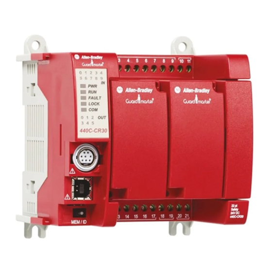
Preface About This Publication The Guardmaster® 440C-CR30 configurable safety relay building block monitors the status of the 440C-CR30 safety relay through a Modbus RS-232C interface. This quick start provides instructions for how to connect the Micro800® programmable logic controller (PLC) with the safety relay for status updates. Use this quick start to configure a monitoring system for your 440C-CR30 safety relay. -
Page 8: Terminology
Preface Terminology Term (Abbreviation) Definition Application Sequence Programs User-modified programs that work together with the standard-state machine logic to control what the machine does while in the abort, clear, reset, run, and stop states. Auto/manual operation When the PanelView™ 800 terminal is in Auto mode, the controller logic controls the machine and monitors machine status. -
Page 9: Building Blocks
These documents contain additional information concerning related products from Rockwell Automation. Resource Description Guardmaster 440C-CR30 Software Configurable Safety Relay Provides information on how to configure a Guardmaster 440C-CR30 configurable safety relay to communicate Quick Start Guide, publication 440C-QS001 with a PanelView 800 terminal via Modbus communication protocol. - Page 10 Preface Notes: Rockwell Automation Publication CC-QS038A-EN-P - August 2015...
-
Page 11: Before You Begin
Chapter Guardmaster 440C-CR30 Configurable Safety Relay Setup This chapter provides information for how to configure the hardware for the 440C-CR30 safety relay. Before You Begin • Review the Getting Started Connected Components Accelerator Toolkit with System Design Assistant Quick Start, publication CC-QS035. -
Page 12: Follow These Steps
Chapter 1 Guardmaster 440C-CR30 Configurable Safety Relay Setup Follow These Steps To configure your 440C-CR30 safety relay, complete these steps. Start Connect the USB Cable to the Safety Relay on page Configure the Communication Settings on page Review the 440C-CR30 Software... -
Page 13: Connect The Usb Cable To The Safety Relay
Guardmaster 440C-CR30 Configurable Safety Relay Setup Chapter 1 Connect the USB Cable to the Safety Relay Connect a USB cable between the safety relay and your personal computer. The driver for the safety relay is automatically installed. If the driver did not install, unplug the USB cable and plug it in again. -
Page 14: Quick Start Guide
Chapter 1 Guardmaster 440C-CR30 Configurable Safety Relay Setup 4. To configure the communication parameters, select Serial Port. 5. From the Common Settings pull-down menu lists, choose these options: • Driver: Modbus RTU • Baud Rate: 19200 • Parity: None 6. Download the configuration to the safety relay. -
Page 15: Before You Begin
Chapter System Validation This chapter provides information for how to configure the controller and human machine interface (HMI) so the devices are communicating correctly. After the configuration is complete, you can validate the system for monitoring the status of the 440C-CR30 safety relay. Before You Begin •... -
Page 16: Follow These Steps
Chapter 2 System Validation Follow These Steps To validate your system, complete these steps. Start Review the System Download Your Program to the Overview on page Controller on page Configure the Controller Configure the IP Address of Your Communication Ports on page PanelView 800 Terminal on page Transfer Your HMI Application Configure the PanelView 800... -
Page 17: Review The System Overview
System Validation Chapter 2 Review the System Overview The PanelView 800 Graphic Terminal can be connected to the Micro800 controller with a CIP serial or CIP-on-Ethernet connection: • For a CIP serial connection, use a 1761-CBL-PM02 cable to connect the PanelView 800 terminal to the embedded serial port of the Micro800 controller. - Page 18 Chapter 2 System Validation 440C-CR30 Safety Relay Connector Micro800 Controller Terminal Pin 7 Pin 4 Pin 2 Figure 3 - Connection for Micro850 and 440C-CR30 Safety Relay IP Address: 192.168.1.2 Micro850 IP Address: 192.168.1.3 Ethernet Cable 440C-CR30 Safety Relay 1761-CBL-HM02 Figure 4 - Connection for Micro830 and 440C-CR30 Safety Relay Micro830 1761-CBL-PM02...
-
Page 19: Configure The Controller Communication Ports
System Validation Chapter 2 Configure the Controller Communication Ports By default, the 440C-CR30 safety relay serial communication port has these communication settings. Figure 5 - Default Communication Configuration for the 440C-CR30 Safety Relay To communicate with the 440C-CR30 safety relay, you must configure the embedded serial port or serial plug-in module of the Micro800 controller with these configuration settings. -
Page 20: Configure The Panelview 800 Terminal Communication Settings
Chapter 2 System Validation Configure the PanelView 800 Terminal Communication Settings To modify these settings in the default Connected Components Workbench project, follow these steps. 1. To open the PanelView 800 application editor, in the Project Organizer double-click the PanelView 800 device icon. The PanelView 800 Communication Settings pane appears in the main project window. - Page 21 System Validation Chapter 2 For CIP-on-Ethernet communication, configure the settings that are shown here. Rockwell Automation Publication CC-QS038A-EN-P - August 2015...
-
Page 22: Connect Your Devices
Chapter 2 System Validation Connect Your Devices There are three network layouts that are identified in Review the System Overview on page 17. In this Quick Start, we picked the Connection with CIP-Ethernet for our application example. Figure 7 - Device Connections IP Address: 192.168.1.2 IP Address: 192.168.1.3 Ethernet... - Page 23 System Validation Chapter 2 To modify the settings for the project that are generated from CCAT version 2 or the project Starting_CR30_M800_r8 downloaded from the Rockwell Automation® sample code website, follow these steps. 2. From the project organizer, open the local variables of <device name> M800_CR30_Sts. 3.
- Page 24 Chapter 2 System Validation 5. In your Connected Components Workbench project, from the Project Organizer, right-click your controller icon and choose Build. 6. When the program is finished building, check the Output pane at the bottom of your project window for a build success message.
- Page 25 System Validation Chapter 2 8. From the Connection Browser, select your controller and click OK. • For USB connection. • For Ethernet connection. 9. If prompted to change the controller mode to Remote Program mode, click Yes. Rockwell Automation Publication CC-QS038A-EN-P - August 2015...
-
Page 26: Configure The Ip Address Of Your Panelview 800 Terminal
Chapter 2 System Validation Configure the IP Address of Your PanelView 800 Terminal To configure a static IP address on the PanelView 800 terminal, follow these steps. 1. From the Main menu, press Communication to open the Communication screen. 2. Press Set Static IP Address. 3. - Page 27 System Validation Chapter 2 3. Select the PanelView 800 terminal and click OK. 4. Verify that the download completed successfully. 5. From the Main menu of your PanelView 800 terminal, press File Manager. 6. On the File Manager screen, select Internal as your Source. 7.
-
Page 28: Validate Your System
Chapter 2 System Validation Validate Your System In this section, you review the Machine Functions screen and explore the Status and Command screens to test the manual control of the building block. Understand the Machine Functions Screen The Machine Functions screen is the screen that links to the installed building blocks. When this screen is first loaded, you can complete the following tasks: •... - Page 29 System Validation Chapter 2 Terminal Name Enter a description of the connection or the name of the safety device that is connected to the corresponding terminal. IN_0 IN_1 IN_2 IN_3 IN_4 IN_5 IN_6 IN_7 IN_8 IN_9 IN_10 IN_11 IO_12 IO_13 IO_14 IO_15 IO_16...
-
Page 30: Understand The Status Screen
Chapter 2 System Validation 5. At any time, press X in the top-right corner to return to the previous screen and press the Next page button to configure the terminals on the next page. 6. When you arrived at the last configuration page, press the Config Done button. The IO_Sts page button appears. - Page 31 System Validation Chapter 2 Table 1 - 440C-CR30 Safety Relay Status Indicators Terminal Name Gray Green IN_0 IN_1 IN_2 IN_3 IN_4 IN_5 Not applicable. IN_6 IN_7 IN_8 IN_9 IN_10 IN_11 IO_12 IO_13 IO_14 A cross fault occurred at the respective terminal.
-
Page 32: Understand The Fault Screens
Chapter 2 System Validation Understand the Fault Screens There are two types of fault screens. A generic fault screen that shows the overall fault status, and a minor fault screen that reports the minor fault details. This generic fault screen reports the type of major fault and indicates which terminal experienced a minor fault. When there is a major fault, the details of the fault appear on this screen. -
Page 33: Verify The Configuration Screens
System Validation Chapter 2 Verify the Configuration Screens Based on the safety configuration information in Guardmaster 440C-CR30 Software Configurable Safety Relay Quick Start Guide, publication 440C-QS001, verify that the I/O is configured as shown in Figure 10 through Figure 12. Press Next Page to go to the different configuration screens. -
Page 34: Verify The Status Screen
Chapter 2 System Validation Verify the Status Screen Based on the safety configuration information in Guardmaster 440C-CR30 Software Configurable Safety Relay Quick Start Guide, publication 440C-QS001, verify that the terminal status is correct as shown in Figure 13 through Figure When the emergency stop and safety gate are at their safe position, the input status for these devices is green. - Page 35 System Validation Chapter 2 Perform a Reset To perform a reset, follow these steps. 1. To perform a reset, use Connected Components Workbench software to go online with the controller and change the Terminal variable in the M800_CR30_Sts program. 2. In the M800_CR30_Sts program, change the Terminal variable from 0 to 1 and then back to 0. Changing the Terminal variable is like triggering bit zero of the Modbus serial input data of the 440C-CR30 safety relay to activate a safety reset.
-
Page 36: Troubleshoot A Wiring Fault
Chapter 2 System Validation Troubleshoot a Wiring Fault To troubleshoot a wiring fault, follow these steps. 1. To simulate a wire break fault, remove the wire from terminal 1. 2. Press Fault Help to access the help screen for more information. The indicator numbers represent the Safety Monitoring Function (SMF) from the safety logic. - Page 37 System Validation Chapter 2 3. Press Minor Fault to access the fault detail. The Minor Fault Help screen reports a Fault Bit 2. The description of this fault corresponds to the type of device that is connected. In this example, SMF 1 is an emergency stop button (a 2-channel device). Therefore, see the description for the 2-channel device.
- Page 38 Chapter 2 System Validation Notes: Rockwell Automation Publication CC-QS038A-EN-P - August 2015...
- Page 39 Appendix 440C-CR30 Configurable Safety Relay User-defined Function Block This appendix describes the available User-defined Function Block (UDFB) and the associated inputs and outputs. This UDFB reads the status of the 440C-CR30 safety relay and displays the status in an intuitive manner. Figure 15 - RA_MDBUS_CR30_STS_UDFB User-defined Function Block Rockwell Automation Publication CC-QS038A-EN-P - August 2015...
- Page 40 Appendix A 440C-CR30 Configurable Safety Relay User-defined Function Block Table 2 - RA_MDBUS_CR30_STS_UDFB Parameter Name Description Data Type FBEN FALSE = The function block is not activated. BOOL TRUE = The function block is activated. FALSE -> TRUE = Initialize or Reset the function block. Channel Indicates which communication port is used.
- Page 41 Description Data Type CR30_STS An array of DINT that consolidates the Modbus statuses of the 440C-CR30 safety relay. This parameter lets other Allen-Bradley® Array controllers read the status through CIP messaging. Each array data represents the output of this UDFB. This list corresponds to the UDFB output of each array.
- Page 42 Appendix A 440C-CR30 Configurable Safety Relay User-defined Function Block Table 3 - CR30_IO_STS Parameter Name Description Data Type P1_Input_Sts Indicates plug-in 1 input status. For example, bit 0 represents the status of input 0, and bit 1 represents the status of SINT input 1, and so on.
- Page 43 Appendix Global Variables This appendix contains the global variables that are used for user program interfacing. Table 5 - Global Variables Variable Name Variable Description Data Type Safety_Sts_SMF_Fault Indicates the fault status of each SMF device that is configured in the 440C-CR30 safety relay. For example, bit 0 DINT represents the fault status of SMF 1, and bit 1 represents the fault status of SMF 2, and so on.
- Page 44 An array of DINT that consolidates the Modbus statuses of the 440C-CR30 safety relay. This variable allows DINT other Allen-Bradley controllers to read the status through CIP messaging. Each array data represents the output of this UDFB. This list corresponds to the UDFB output to each array.
- Page 45 Global Variables Appendix B Table 5 - Global Variables (Continued) Variable Name Variable Description Data Type Safety_P1_IO_Des An 8-array variable that represents the names of up to eight terminals for plug-in 1. STRING [0] = IN_1 [1] = IN_2 [2] = IN_3 [3] = IN_4 [4] = OUT_1 [5] = OUT_2...
- Page 46 Appendix B Global Variables Table 5 - Global Variables (Continued) Variable Name Variable Description Data Type Safety_Sts_SMF Indicates the status of each SMF device that is configured in the 440C-CR30 safety relay. For example, bit 0 DINT represents the status of SMF 1, and bit 1 represents the status of SMF 2, and so on. TRUE = The corresponding device is configured and activated.
- Page 48 Rockwell Automation Support Rockwell Automation provides technical information on the Web to assist you in using its products. http://www.rockwellautomation.com/support you can find technical and application notes, sample code, and links to software service packs. You can also visit our Support Center at https://rockwellautomation.custhelp.com/ for software updates, support chats and forums, technical information, FAQs, and to sign up for product notification updates.
Need help?
Do you have a question about the Guardmaster 440C-CR30 and is the answer not in the manual?
Questions and answers