Table of Contents
Advertisement
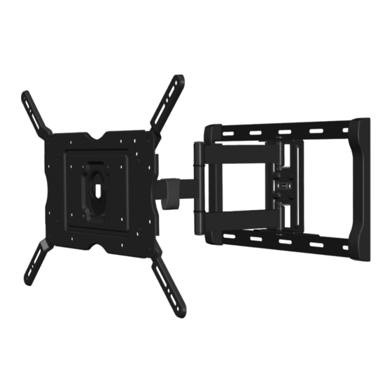
ARTICULATING TV WALL MOUNT FOR MOST 32-INCH TO 80-INCH TVS
INSTRUCTION MANUAL
SUPPORT DE MONTAGE MURAL ARTICULÉ POUR LA PLUPART DES TÉLÉVISEURS DE 32 À 80 POUCES
MANUEL D'INSTRUCTIONS
TV-GELENK-WANDHALTERUNG FÜR DIE MEISTEN FERNSEHER VON 32 ZOLL (81 CM) BIS 80 ZOLL (203 CM)
DIAGONALE
ANLEITUNGSHANDBUCH
STAFFA DI MONTAGGIO A PARETE CON ARTICOLAZIONE PER LA MAGGIOR PARTE DEI TELEVISORI DA
32-INCH (32 POLLICI) A 80-INCH (80 POLLICI)
MANUALE DI ISTRUZIONI
SOPORTE DE TV PARA PARED ARTICULADO PARA LA MAYORÍA DE LAS PANTALLAS DE 32 A 80 IN
(81 A 203 CM)
MANUAL DE INSTRUCCIONES
ASIN: B01KBEOM2G
1
Advertisement
Table of Contents

Related Manuals for AmazonBasics B01KBEOM2G


Summary of Contents for AmazonBasics B01KBEOM2G
- Page 1 STAFFA DI MONTAGGIO A PARETE CON ARTICOLAZIONE PER LA MAGGIOR PARTE DEI TELEVISORI DA 32-INCH (32 POLLICI) A 80-INCH (80 POLLICI) MANUALE DI ISTRUZIONI SOPORTE DE TV PARA PARED ARTICULADO PARA LA MAYORÍA DE LAS PANTALLAS DE 32 A 80 IN (81 A 203 CM) MANUAL DE INSTRUCCIONES ASIN: B01KBEOM2G...
-
Page 2: Specifications
SPECIFICATIONS Display Size: 32” to 80” Maximum Load: 130 lbs. (60 kg) Mounting Pattern: 100x100, 200x100, 200x200, 300x200, 300x300, 400x200, 400x300, 400x400, 600x400 Tilt Range: -5° to 10° down Profile: 2. 5” x 19.9” (65mm x 505mm) CAUTION! This product is for indoor use only! Never use the mount outdoors! CAUTION! This product is for private household use only and therefore may not be used in public places like restaurants or hotels. - Page 3 • Examine the wall you want to install the mount to before you start installation. Make sure that there are no hidden power supply cables, gas pipes, water pipes or other objects hidden in the wall that might be hit by the drill, screws or other hardware. •...
- Page 4 SPÉCIFICATIONS Grandeur de l’écran : 32 po à 80 po Charge maximale : 60 kg (130 lbs.) Modèle de montage : 100x100, 200x100, 200x200, 300x200, 300x300, 400x200, 400x300, 400x400, 600x400 Plage verticale : -5° à 10° vers le bas Profil : 65mm x 505mm (2. 5” x 19.9”) MISE EN GARDE! Ce produit est destiné uniquement à une utilisation en intérieur! Ne jamais utiliser le support en extérieur! MISE EN GARDE! Ce produit est destiné...
- Page 5 6. Choisissez le bon endroit pour installer la plaque murale. • Assurez-vous que le mur puisse supporter au moins 4 fois le poids de la télévision et du support. Si nécessaire, demandez à un technicien qualifié de renforcer la paroi. • Examinez le mur sur lequel vous souhaitez installer le support avant de commencer l’installation.
- Page 6 SPEZIFIKATIONEN Bildschirmgröße: 32 “ bis 80“ Maximalgewicht: 60 kg (130 lbs.) Einbaus- chablone: 100x100, 200x100, 200x200, 300x200, 300x300, 400x200, 400x300, 400x400, 600x400 Neigungsbereich: -5° bis 10° nach unten Profil: 65mm x 505mm (2. 5” x 19.9”) ACHTUNG! Dieses Produkt ist nur für den Innengebrauch! Verwenden Sie die Halterung niemals im Freien! ACHTUNG! Dieses Produkt ist für den ausschließlich für den Privathaushalt und kann daher nicht an öffentlichen Orten wie Restaurants oder Hotels verwendet werden.
- Page 7 6. Wählen Sie die geeignete Stelle für die Installation der Wandhalter- ung. • Stellen Sie sicher, dass die Wand das vierfache Gewicht des Fern- sehers und der Halterung tragen kann. Falls nötig, holen Sie einen qualifizierten Techniker, um die Wand zu verstärken. • Überprüfen Sie die Wand, auf der Sie die Halterung montieren wollen, vor Installationsbeginn.
- Page 8 SPECIFICHE Dimensione schermo: da 32” a 80” Carico massimo: 60 kg (130 lbs.) Dima di montaggio: 100x100, 200x100, 200x200, 300x200, 300x300, 400x200, 400x300, 400x400, 600x400 Gamma di inclinazione: da -5° a 10° verso il basso Profilo: 65mm x 505mm (2. 5” x 19.9”) ATTENZIONE! Questo prodotto è solo per uso interno! Non utilizzare mai il supporto all’esterno! ATTENZIONE! Questo prodotto è...
- Page 9 6. Scegliere il luogo corretto per installare la piastra a parete. • Accertarsi che la parete sia in grado di sostenere almeno 4 volte il peso della TV e del supporto. Se necessario, far rinforzare la parete da un tecnico qualificato. •...
- Page 10 ESPECIFICACIONES Dimensione schermo: da 32” a 80” Carico massimo: 60 kg (130 lbs.) Dima di montaggio: 100x100, 200x100, 200x200, 300x200, 300x300, 400x200, 400x300, 400x400, 600x400 Gamma di inclinazione: da -5° a 10° verso il basso Profilo: 65mn x 505mm (2. 5” x 19.9”) PRECAUCIÓN Este producto está diseñado solamente para usarse en interi- ores. Nunca use el montaje al aire libre. PRECAUCIÓN Este producto está...
- Page 11 6. Elija el lugar adecuado para instalar la placa de pared. • Asegúrese de que la pared pueda soportar por lo menos 4 veces el peso del televisor y del soporte. Si es necesario, pida a un técnico calificado que refuerce la pared. •Examine la pared en la que desea instalar el soporte antes de empezar la instalación.
- Page 12 Placa del monitor, 1 (ES) (ES) (EN) INSTALLATION TEMPLATE (FR) GABARIT DE POSE (DE) INSTALLATIONSSCHABLONE ASIN B01KBEOM2G (IT) SCHEMA DI INSTALLAZIONE (ES) PLANTILLA DE INSTALACIÓN (EN) Check Level Line (FR) Ligne de Niveau (DE) Horizontale Ausrichtung prüfen (IT) Verificare che lo schema sia parallelo al suolo (ES) Revise la línea de nivel...
- Page 13 (EN) INCLUDED PARTS (FR) PIÈCES INCLUSES PARTES INCLUIDAS INCLUDED PARTS PIÈCES INCLUSES (DE) IM LIEFERUMFANG ENTHALTENE TEILE IM LIEFERUMFANG PARTI INCLUSE (IT) PARTI INCLUSE ENTHALTENE TEILE (ES) PARTES INCLUIDAS [A] M4 x 12mm, 4 [C] M4 x 30mm, 4 [J] M6 x 14mm, 4 [L] M6 x 35mm, 4 [M] M8 x 20mm, 4 [OS] M8 x 38mm, 4...
- Page 14 (EN) NECESSARY TOOLS (FR) OUTILLAGE NÉCESSAIRE NECESSARY OUTILLAGE HERRAMIENTAS TOOLS NÉCESSAIRE NECESARIAS (DE) ERFORDERLICHE WERKZEUGE ATTREZZI ERFORDERLICHE (IT) ATTREZZI NECESSARI NECESSARI WERKZEUGE (ES) HERRAMIENTAS NECESARIAS (EN) Phillips-head Screwdriver (EN) Ratchet Set (FR) Tournevis à tête Phillips (FR) Clé à cliquet à douilles (DE) Kreuzschlitzschraubenzieher (DE) Schaltklinke Hilfsmittel (IT) Cacciavite Phillips...
- Page 15 (EN) ATTACHING THE MONITOR PLATE [MP] (FR) FIXER LA PLAQUE DE MONITEUR [MP] (DE) BEFESTIGUNG DER MONITOR-PLATTE [MP] (IT) FISSAGGIO DELLA PIASTRA PER LO SCHERMO [MP] (ES) CÓMO FIJAR LA PLACA DEL MONITOR [MP] (EN) SELECT THE CORRECT SCREW Before beginning, test several of the screws in your hardware kit to find the correct size and length for your television.
- Page 16 (EN) REMOVE THE SECURITY SCREWS (FS) The Monitor Plate (MP) was shipped pre-installed to the Extension Arm (EA). Before you begin, remove the two Security Screws (FS) as shown in and separate the two components. Do not throw out the security screws. (FR) ENLEVER LES VIS DE SÉCURITÉ...
- Page 17 [FS] [HT]...
- Page 18 (EN) DECIDE IF ADAPTER PLATES [AP] ARE NECESSARY Compare to the mounting holes on the back of your television. (FR) DÉCIDER SI DES PLAQUES D’ADAPTATION [AP] SON NÉCESSAIRES Comparer aux trous de fixation au dos du téléviseur. (DE) ENTSCHEIDEN SIE SICH, OB ADAPTER-PLATTEN [AP] ERFORDERLICH SIND Vergleichen Sie sie mit den Montagelöchern auf der Rückseite Ihres Fernsehers. (IT) DECIDERE SE LE PIASTRE-ADATTORE [AP] SONO NECESSARIE Verificare la corrispondenza tra la posizione dei fori sul retro del televisore e il supporto stesso.
- Page 19 (EN) IF USING THE ADAPTER PLATES [AP]: Attach the Adapter Plates [AP] to the Monitor Plate [MP] using eight M8 x 10mm Screws [BE]. (FR) SI LES PLAQUES D’ADAPTATION [AP] SONT UTILISÉES : Fixer les plaques d’adaptation [AP] à la plaque de moniteur [MP] à l’aide de huit vis M8 x 10mm [BE].
- Page 20 (EN) ATTACH MONITOR PLATE [MP] TO TELEVISION Attach the Monitor Plate [MP] using the correct TV Mounting Screws [A, J, or M] and Washers [R or S] as shown. Do not place the Washers between the monitor plate and the TV. (FR) FIXER LA PLAQUE DE MONITEUR [MP] AU TÉLÉVISEUR Fixer la plaque de moniteur [MP] avec les vis [A, J, ou M] de fixation de TV et les rondelles [R ou S] correctes comme sur l’illustration.
- Page 21 (EN) Use spacers [E or P] if the Monitor Plate [MP] does not fit firmly against the back of the television, such as when the back of the television is curved, contains larger re- cessed mounting holes, or some other obstruction is in the way. The Monitor Plate must rest securely on the spacers, and should not be loose. Use longer screws [C, L or OS]. (FR) Utiliser les douilles d’espacement [E ou P] si la plaque de moniteur [MP] où...
- Page 23 (EN) INSTALLING THE WALL MOUNT IN WOOD (FR) POSER LE SUPPORT MURAL SUR DU BOIS (DE) INSTALLATION DER WANDBEFESTIGUNG IN HOLZ (IT) INSTALLAZIONE DEL SUPPORTO A PARETE SU LEGNO (ES) CÓMO INSTALAR EL SOPORTE DE PARED EN MADERA (EN) FIND THE WOOD STUD Using a stud finder, find the exact location of the stud to which you want to attach the wall mount.
- Page 24 (EN) DETERMINE HEIGHT LOCATION OF TELEVISION Measure the distance from the bracket holes to the top and bottom of the TV to determine the center mounting position. Measure from the floor up, and make small marks on the wall to help you determine the desired TV height. Using a level, line up the Installation Template [IT] with your pencil markings and tape it into place.
- Page 25 (EN) INSTALLATION TEMPLATE (FR) GABARIT DE POSE (DE) INSTALLATIONSSCHABLONE ASIN B01KBEOM2G (IT) SCHEMA DI INSTALLAZIONE (ES) PLANTILLA DE INSTALACIÓN (EN) Check Level Line (FR) Ligne de Niveau (DE) Horizontale Ausrichtung prüfen (IT) Verificare che lo schema sia parallelo al suolo (ES) Revise la línea de nivel...
- Page 26 (EN) FOR MASONRY INSTALLATIONS, SEE PAGE 30. (FR) POUR UNE POSE SUR DE LA MAÇONNERIE, VOIR PAGE 30. (DE) FÜR INSTALLATIONEN IN MAUERWERK, SIEHE SEITE 30. (IT) PER INSTALLAZIONI A MURO, VEDERE A PAGINA 30. (ES) PARA INSTALACIONES EN MAMPOSTERÍA CONSULTE LA PÁGINA 30. (EN) DRILL PILOT HOLES Follow directions on the Installation Template (IT) carefully.
- Page 27 (EN) INSTALLATION TEMPLATE (FR) GABARIT DE POSE (DE) INSTALLATIONSSCHABLONE ASIN B01KBEOM2G (IT) SCHEMA DI INSTALLAZIONE (ES) PLANTILLA DE INSTALACIÓN (EN) Check Level Line (FR) Ligne de Niveau (DE) Horizontale Ausrichtung prüfen (IT) Verificare che lo schema sia parallelo al suolo (ES) Revise la línea de nivel...
- Page 28 (EN) INSTALL THE EXTENSION ARM (EA) Install the Extension Arm (EA) using four Lag Bolts (BT) with Washers (BW) in the “A”, “B”, “C” and “D” holes. Do not tighten Lag Bolts completely. Use a Level to make sure the Extension Arm is vertically level. Finally, tighten all Lag Bolts completely (do not over tighten!).
- Page 29 [EA] [BW] [BT] (EN) DO NOT OVER TIGHTEN LAG BOLTS [TS]! (FR) NE PAS FORCER SUR LES TIRE-FOND [TS] ! (DE) ZIEHEN SIE DIE ANKERBOLZEN [TS] NICHT ZU FEST! (IT) NON SERRARE ECCESSIVAMENTE I BULLONI [TS]! (ES) NO AJUSTE DEMASIADO LOS TIRAFONDOS [TS]!
- Page 30 Fissare lo (EN) INSTALLATION TEMPLATE schema al muro con nastro (FR) GABARIT DE POSE (DE) INSTALLATIONSSCHABLONE ASIN B01KBEOM2G (IT) SCHEMA DI INSTALLAZIONE (ES) PLANTILLA DE INSTALACIÓN (EN) Check Level Line (FR) Ligne de Niveau (DE) Horizontale Ausrichtung prüfen (IT) Verificare che lo schema sia parallelo al suolo (ES) Revise la línea de nivel...
- Page 31 (EN) DRILL PILOT HOLES Carefully drill four holes using a 3/8” (or 9.5 mm) masonry drill bit in the “A”, “B”, “C”, and “D” locations noted on the Installation Template. Each hole should be at least 3-3/4” (95 mm) deep. (FR) PERCER LES TROUS GUIDES Percer soigneusement quatre trous avec une mèche à maçonnerie de 3/8 po (ou 9.5 mm aux emplacements notés « A » « B » « C » et « D » sur le gabarit de pose. Chaque trou doit être d’au moins 95 mm (3-3/4 po) de profond. (DE) FÜHREN SIE VORBOHRUNGEN DURCH Bohren Sie sorgfältig vier Löcher mit einer 9.5 mm großen Bohrerspitze für Mauerw- errk in die “A”, “B”, “C”, und “D”...
- Page 32 (EN) DO NOT DRILL INTO MORTAR JOINTS! DRILL TOP HOLES AT LEAST 1" (25.4 MM) FROM THE JOINTS. USE A NEW DRILL BIT TO ENSURE OPTIMUM HOLDING ABILITY. DO NOT USE A HAMMER DRILL! (FR) NE PAS PERCER DANS LES JOINTS DE MORTIER ! PERCER LES TROUS SUPÉRIEURS À...
- Page 33 (EN) INSERT ANCHORS Remove Template [IT] and insert Anchors [U10]. (FR) ENFONCER LES CHEVILLES Enlever le gabarit [IT] et enfoncer des chevilles d’ancrage [U10]. (DE) DÜBEL EINFÜGEN Entfernen Sie die Schablone [IT] und führen Sie Dübel [U10]. (IT) INSERIRE I TASSELLI Togliere lo schema [IT] e inserire i tasselli [U10].
- Page 34 (EN) INSTALL THE EXTENSION ARM (EA) Install the Extension Arm (EA) using four Lag Bolts (BT) with Washers (BW) in the “A”, “B”, “C” and “D” holes. Do not tighten Lag Bolts completely. Use a Level to make sure the Extension Arm is vertically level. Finally, tighten all Lag Bolts completely (do not over tighten!).
- Page 35 [U10] [EA] [BW] [BT] (EN) DO NOT OVER TIGHTEN LAG BOLTS [TS]! (FR) NE PAS FORCER SUR LES TIRE-FOND [TS] ! (DE) ZIEHEN SIE DIE ANKERBOLZEN [TS] NICHT ZU FEST! (IT) NON SERRARE ECCESSIVAMENTE I BULLONI [TS]! (ES) NO AJUSTE DEMASIADO LOS TIRAFONDOS [TS]!
- Page 36 (EN) PREPARE THE MOUNT FOR INSTALLING THE TV Before you place the television on the wall, first move the Extension Arm [EA] into the straight extended position and make sure the Wall Plate [WP] is level on the wall. Check the Tilt Adjustment. It needs to be tight so it will not tilt during installation.
- Page 37 [HT]...
- Page 38 (EN) MOUNT THE TELEVISION With the help of an assistant, lift the television and guide the Monitor Plate [MP] onto the Extension Arm [EA] as shown. Once safely on the mount, continue to hold the TV securely while installing the Security Screws [FS], using the Hex Tool [HT].
- Page 39 [MP] [EA] [HT] (EN) Exercise caution when removing the television from the mount to avoid equipment damage or personal injury. (FR) Lors du décrochage du téléviseur, faire preuve de précaution pour éviter les dommages matériels et corporels. (DE) Gehen Sie vorsichtig bei der Abnahme des TVs von der Befestigung um, um das Gerät nicht zu beschädigen oder um keine Körperverletzungen zu verursachen.
- Page 40 (EN) USING THE TILT FEATURE Once the television is secured on the Extension Arm (EA), you can adjust the tilt of the television by loosening both Tilt Screws using the Hex Tool (HT). Tilt the television into the desired position, then fully tighten the Tilt Screws again with the Hex Tool.
- Page 41 [MP] [EA] [HT]...
- Page 42 (EN) ADJUST THE TV LEVEL Once the television is secured on the Extension Arm (EA), you can adjust the level of the television by slightly loosening the two Leveling Screws on the back of the Extension Arm (EA) with the Hex Tool (HT).
- Page 43 [EA] [FS] [MP] [HT]...
- Page 44 (EN) USING THE CABLE MANAGEMENT FEATURE Feed the Audio Video cables through the Cable Management Cover (CC) as shown. Attach the Cover to the bottom portion of the Extension Arm (EA) by pressing upward until the Cover snaps into place. Remove extra cables if the Cover will not properly attach.
- Page 45 [EA] [CC]...
-
Page 46: Warranty Information
Warranty Information To ob tain a c opy o f t he warrant y f or t his p ro duc t: Visit amazon.com/AmazonBasics/Warranty — o r — Contact Customer Service at 1-866-216-1072 Feedback Love it? Hate it? Let us know wit h a cus tomer review. - Page 47 Vous adorez? Vous détestez? L aissez-no u s vo t re a vis . AmazonBasics s’engage à fournir des produits qui prennent en compte l’avis de la clientèle et répondent aux attentes élevées qu’elle formule. Nous vous encourageons à nous laisser un commentaire afin de nous faire part de votre expérience du produit.
- Page 48 Sa gen S ie es un s mi t ei ne r Ku nde n re z e n s io n . AmazonBasics möchte Produkte anbieten, die den hohen Erwartungen unserer Kunden gerecht werden. Schreiben Sie eine Rezension und erzählen Sie uns von Ihren Erfahrungen mit dem Produkt.
- Page 49 P er ot t e n e re u na cop i a d el l a gar a n z i a pe r qu e s to pro do tt o : Visitare amazon.com/AmazonBasics/Warranty — op pu re —...
- Page 50 Información sobre la garantía Par a ob te ne r u na c o pi a de l a g ar ant ía de este produ cto: Visita amazon.com/AmazonBasics/Warranty — o — ponte en contacto con el servicio de Atención al Cliente a través del +1-866-216-1072 Opinión...
- Page 52 a m a z o n . c o m / A m a z o n B a s i c s M A D E I N C H I N A R E V. 1 1 0 7 1 6...
Need help?
Do you have a question about the B01KBEOM2G and is the answer not in the manual?
Questions and answers
Minting pattern for Phillips 55” tv