Advertisement
Quick Links
Advertisement

Related Manuals for Honeywell THP9045A


Summary of Contents for Honeywell THP9045A
- Page 1 Wire Saver Installation Wire Saver THP9045A (Optional – for thermostats without 24-volt C wire)
- Page 2 About the Wire Saver A wire saver acts as a splitter for applications that do not include a 24-volt C wire. If your heating/cooling system does not include a C wire, install the wire saver in or near the main unit (furnace, air handler) of your heating/cooling system.
- Page 3 Step 1 Verify that you need a wire saver Important! Ensure that the system is OFF (Quick Start Guide Step 1.1) Complete Steps 1.1 through 1.6 in the Quick Quick Start Guide Start Guide. Wi-Fi Programmable Thermostat RTH6500WF Wi-Fi Series •...
- Page 4 Step 2 Wire the thermostat At your new thermostat, for each wire: Remove metal jumper only if you have both R 1. Loosen the screw, insert wire on inside edge and Rc wires of thermostat terminal, then tighten screw. 2. Verify wire is firmly secured by gently pulling on wire.
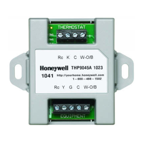
- Page 5 Peel paper from one side of the included two- sided mounting tape. THERMOSTAT c. Attach the sticky side to a suitable surface Rc K C W-O/B THP9045A 1023 http://yourhome.honeywell.com (such as the furnace wall or floor) that is close 1326 1-800-546-1502...
- Page 6 Step 4 Select a wire configuration Examine the labels on the terminal block for the existing thermostat wires. Determine which of the following combinations matches your setup: a. Single stage system (1 heat and 1 cooling stage) uses wires R or Rc, Y, G, W b.
- Page 7 Step 5 Connect the wire saver Connecting the wire saver involves two main actions: moving some wire connections from the terminal block in your heating/cooling system to the THERMOSTAT terminal block of the wire saver and using the included wire bundle to connect the terminal block on the equipment to the EQUIPMENT block on the wire saver.
- Page 8 5a Wire single-stage equipment 1. Disconnect the R wire from your heating/cooling system’s terminal block. 2. Connect the R wire to the Rc terminal on the THERMOSTAT end of the wire saver. 3. Disconnect the W wire from the heating/cooling system; connect it to W on the THERMOSTAT end of the wire saver.
- Page 9 When you complete the steps above, your wire saver and heating/cooling system will be wired as shown. Wire To Thermostat Saver THERMOSTAT Rc K C W-O/B At Heating/ THP9045A 1023 Cooling System 1326 http://yourhome.honeywell.com 1-800-546-1502 Rc Y G C W-O/B EQUIPMENT WIRE BUNDLE M35229...
- Page 10 5b Wire two-stage heat, single-stage cooling 1. Do not disconnect the W2 wire from your heating/cooling system. 2. Disconnect the R wire from your heating/cooling system’s terminal block. 3. Connect the R wire to the Rc terminal on the THERMOSTAT end of the wire saver. 4.
- Page 11 When you complete the steps in 5b, your wire saver and heating/cooling system will be wired as shown. Wire To Thermostat Saver THERMOSTAT Rc K C W-O/B At Heating/ THP9045A 1023 Cooling System http://yourhome.honeywell.com 1326 1-800-546-1502 Rc Y G C W-O/B EQUIPMENT WIRE BUNDLE To Thermostat...
- Page 12 5c Wire two-stage heat, two-stage cooling 1. Do not disconnect the W2 or Y2 wires from your heating/cooling system. 2. Disconnect the R wire from your heating/cooling system’s terminal block. 3. Connect the R wire to the Rc terminal on the THERMOSTAT end of the wire saver. 4.
- Page 13 When you complete the steps in 5c, your wire saver and heating/cooling system will be wired as shown. Wire To Thermostat Saver THERMOSTAT Rc K C W-O/B At Heating/ THP9045A 1023 Cooling System http://yourhome.honeywell.com 1326 1-800-546-1502 Rc Y G C W-O/B EQUIPMENT WIRE BUNDLE To Thermostat...
- Page 14 G O/B R Rc At Thermostat THERMOSTAT At Heating/ Rc K C W-O/B CONVENTIONAL K Y2 W2 G W Y R Rc THP9045A 1023 Cooling System http://yourhome.honeywell.com 1326 1-800-546-1502 Rc Y G C W-O/B HEAT PUMP AUX/E G O/B R Rc...
- Page 15 Step 6 Close the equipment door Close or put back door to the heating and cooling system so the interlock switch will allow the system to be turned on for the heating/cooling system and thermostat display. Your thermostat display will not turn on if the door/panel is not closed. Step 7 Follow instructions in Quick Start Guide Continue with Step 1.8 in the Quick Start Guide.
- Page 16 33-00042-01 Automation and Control Solutions Honeywell International Inc. 1985 Douglas Drive North Golden Valley, MN 55422 wifithermostat.com ® U.S. Registered Trademark. © 2014 Honeywell International Inc. 33-00042—02 M.S. 06-14 Printed in U.S.A.
Need help?
Do you have a question about the THP9045A and is the answer not in the manual?
Questions and answers