Table of Contents
Advertisement
Advertisement
Table of Contents

Related Manuals for Ridder HortiMaX-Go


Summary of Contents for Ridder HortiMaX-Go
- Page 1 HortiMaX-Go! Installation Manual SV 1.2 24/08/2018 160211MAN060 96000000...
-
Page 2: Panel Pc
Growing Solutions B.V. can assume no responsibility for any errors in this manual or their possible consequences. This product is subject to the General Conditions of Ridder Growing Solutions B.V. This document may not be copied or made public by means of print, photocopy, microfilm or any other process, without the written permission of Ridder Growing Solutions B.V. -
Page 3: Table Of Contents
1.4 Symbols and method of notation 1.4.1 Symbols 1.4.2 Method of notation 1.5 Documentation overview 1.6 Disclaimer 2 Product information 2.1 What is the HortiMaX-Go!? 2.2 Associated components 2.3 System architecture 2.4 Storage and transport 2.5 Removal 3 Installation 3.1 Requirements 3.2 Step-by-step installation and configuration instructions... - Page 4 4.4.2 Valves simultaneously 4.4.3 Calibrating the EC and pH sensors 4.4.4 Setting up flow sensor Appendix A: HortiMaX-Go!-Pro touchscreen Controller 5.1 Panel pc 1 5.2 Panel pc 2 Appendix B: Settings overview 6.1 Alarm settings 6.2 Climate settings 6.2.1 Standard zone measurements 6.2.2 Leeward side...
-
Page 5: Introduction To This Manual
You can manage your Cloudboxes, controllers and app users on our CloudPortal. Purpose The purpose of this manual is to instruct you on how to install the HortiMaX-Go!. Target group This manual is intended for dealers and installers. -
Page 6: Method Of Notation
Scan the QR code to access the online help. help.hortimax-go.com Disclaimer Ridder Growing Solutions has done its best to include up-to-date images and screenshots in this manual. However, the images and screenshots used may differ from the actual ones shown. -
Page 7: Product Information
The HortiMaX-Go! is an easy-to-use and affordable control computer designed specifically for the horticultural sector. With the HortiMaX-Go!, you can control both the irrigation and the climate inside your greenhouse. The HortiMaX-Go! is easy to customize by choosing unique ‘Smart Switches’ that can be installed in a plug-and- play manner. - Page 8 Sensor unit for measuring the ambient temperature and humidity inside the greenhouse. MTV-Go! Smart Switch Individual sensor unit board for MTV-Go!. HortiMaX-Go! CloudBox The HortiMaX-Go! CloudBox enables you to link your controllers to the Internet. Terminal resistor 120Ω resistor for closing the fieldbus.
-
Page 9: System Architecture
System architecture The HortiMaX-Go! features a modular design. Every system is different in terms of the number and types of Smart Switches as well as the number of HortiMaX-Go! controllers. The FertiMiX-Go! is always equipped with a dedicated controller. The illustration below is an example of a HortiMaX-Go! configuration that includes a... -
Page 10: Storage And Transport
In rare cases, however, damage may occur during shipping. That is why you should always check the packaging and the product for damage or signs of rough handling. Please report any damage to the carrier and Ridder Growing Solutions. -
Page 11: Removal
Keep the various components in their original packaging for as long as possible. Removal At the end of its useful life, please return the HortiMaX-Go! to Ridder Growing Solutions or dispose of the HortiMaX-Go! in accordance with local regulations. -
Page 12: Installation
Step-by-step installation and configuration instructions You need to complete steps 1 to 7 in order to install the HortiMaX-Go!. You then need to complete steps 8 to 14 in order to carry out the configuration. Step Description Unpack the required materials and check for defects. -
Page 13: Hortimax-Go! Control Cabinet
Activate the HortiMaX-Go! and the Smart Switches by switching the supply voltage on. When the HortiMaX-Go! is configured for the first time, the display will show start menu. Select the desired language and unit of measurement. Tap confirm ‘ '. -
Page 14: Location And Connection Requirements
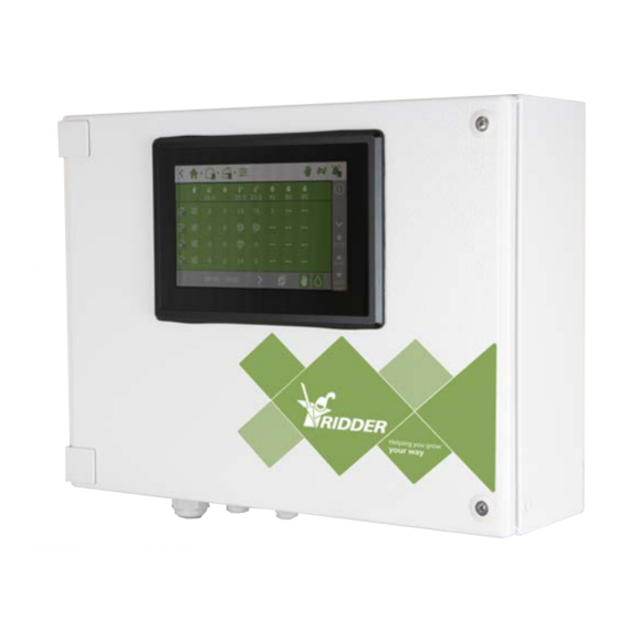
HortiMaX-Go! Figure 3-1: Front view of HortiMaX-Go! 3.3.1 Location and connection requirements Bear in mind the following when choosing a location for the control cabinet: 1. Make sure that the cabinet is easy to access. 2. Keep the cabinet out of direct sunlight, so the display is easy to read. Keep out of reach of rain, condensation water and sprinkler irrigation. -
Page 15: Fieldbus
(also called 'thermal protector contacts'). The Smart Switches can use the collected status information to control the equipment in your greenhouse, and can relay also that information to the central HortiMaX-Go! controller. This greatly enhances the reliability of the system. For example, the system will generate an alarm instantly should something go wrong with your equipment. -
Page 16: Dip Switch
3.4.1 DIP switch Up to 32 Smart Switches can be connected to the HortiMaX-Go!. To install Smart Switches, you first need to assign addresses to the Smart Switches. Each Smart Switch requires a unique address. This address is set with the DIP switch. By moving the small toggle switches (or 'DIPs') up or down, you can set a binary number that will be used as the Smart Switch address. -
Page 17: Led Indicators For Bus Communication
HortiMaX-Go! Setting the DIP switch address Place the product sticker, included with the Smart Switch, in an empty spot on the wiring list. Determine up to which zone the Smart Switch belongs (1 - 8). On the wiring list, place the relevant 'zone sticker' on the line of the Smart Switch next to the ID number. -
Page 18: Led Indicators For Operation
Communication has 1: Red No communication has been continuous been established continuous established with the with the HortiMaX- HortiMaX-Go!. Check whether Go!. a connection can be made. 1: Green Smart Switch control 1: Red Smart Switch control is flashing is active. The Smart... -
Page 19: Location And Connection Requirements
HortiMaX-Go! 3: Green The open end 4: Red The close end position has flashing position has been flashing been reached. (For example, reached. (For the vent is closed.) example: a vent is 100% open.) 5: Green The output is active. -
Page 20: Mtv-Go
5 Watts. MTV-Go! The MTV-Go! is the indoor sensor unit of the HortiMaX-Go!. The MTV-Go! is a special Smart Switch, enclosed in a naturally ventilated dual housing, that measures both the temperature and humidity levels inside the greenhouse. The electronic humidity sensor is located at one end (the bottom end) of the printed circuit board (PCB);... -
Page 21: Representative Location
HortiMaX-Go! Step Description Close the inner housing tightly and reattach it to the top cover. Reattach the outer tube to the top cover. Hang the sensor unit in a representative location inside the greenhouse (see: "Representative location" below). 3.5.2 Representative location The MTV-Go! sensor unit is essential for controlling the climate inside the greenhouse. -
Page 22: Location
HortiMaX-Go! Figure 3-5: Meteo-Go! 3.6.1 Location Install the weather station on a pole (diameter: 25 mm) 2 metres above the greenhouse roof; the Allen bolt should be positioned north. Make sure to choose a location for the Meteo-Go! that is free from shade and not too close to an exhaust such as a chimney. -
Page 23: Network Connection
No peripheral equipment for creating networks is supplied with the HortiMaX-Go!. To create a network, use commonly available devices. If possible, use standard CAT 5 cables or higher and normal patch cables. -
Page 24: Configuration
Configuration This chapter contains more information on how to configure the HortiMaX-Go!. For instructions on how to configure the HortiMaX-Go!, please see the following sections: System settings In order to put the system into operation, you need to set the display language, unit of measurement and the Smart Switches that are con- nected to the system. -
Page 25: Scanning
4.1.2 Scanning The control switches of the HortiMaX-Go! are the Smart Switches. The system needs to know which Smart Switches are present. For this reason, you need to scan the system. You can do this from the scanning screen. This screen opens automatically when you use your system for the first time. -
Page 26: Configuration Settings
HortiMaX-Go! Tap the Smart Switch that you want to disable/remove. A pop-up menu appears. Select the desired status. The status has been changed. If necessary, you can restore the previous configuration status. To do this, complete the above steps again and select the 'Recover' status. -
Page 27: System Time
Current time zone The HortiMaX-Go! cannot automatically determine when Summer Time (Daylight saving time) and Winter Time (standard time) start and end. This is because Summer Time and Winter Time do not take effect everywhere at the same time and some countries have different rules regarding these time adjustments. -
Page 28: Location
Figure 4-5: The 'GPS coordinates for weather readings' setting is enabled Enter manually A GPS location can be indicated in various ways. The HortiMaX-Go! uses the 'signed degrees' format. This means that: a positive longitude is used for the Eastern Hemisphere (this is east of Green- wich). -
Page 29: Network Address
4.2.3 Network address If the HortiMaX-Go! has been connected to the network correctly, the IP address will be retrieved automatically. The system uses the router's DHCP service to set the IP address. It is not possible to set the IP address manually. -
Page 30: Climate Settings
HortiMaX-Go! EXAMPLE A valve only provides readout information, such as 'valve status'. In contrast, the flow meter has both configuration settings and a readout screen. This means that you can set the K-factor and view the flow rate for the flow meter. -
Page 31: Opening Direction
HortiMaX-Go! Connecting the end contacts has a key advantage: Your controller will be able to better determine the current position of the motor. When the limit contacts have been connected, the run times can be determined automatically. 1. Connect the end contacts. -
Page 32: Valves Simultaneously
HortiMaX-Go! You have assigned valves to a valve group. Figure 4-9: Assigning valves The irrigation program enables you to use a separate valve group for each valve. 4.4.2 Valves simultaneously Use the Valves simultaneously setting to specify how many valves may open simultaneously. - Page 33 HortiMaX-Go! Calibration Every twelve months Every six months Calibration solution 1.4 and 5.0. 7.0 and 4.0. Calibration steps for EC sensor The calibration process involves a few simple steps; the controller will describe the steps that you need to carry out.
-
Page 34: Setting Up Flow Sensor
HortiMaX-Go! Start calibration. Tap confirm ‘ '. Place sensor in pH 7.0. Tap confirm ‘ '. Measure pH 7.0. Stir the sensor during the wait time so that the liquid will remain homogeneous. Measurement complete. Tap confirm ‘ '. Place sensor in pH 4.0. -
Page 35: Appendix A: Hortimax-Go!-Pro Touchscreen Controller
HortiMaX-Go! Appendix A: HortiMaX-Go!-Pro touchscreen Controller 1P230V + N + PE 50Hz Panel PC 1 Excerpt - page 4. Panel PC 2 Excerpt - page 4. - Page 36 [RED] [BLUE] [YELLOW/GREEN] [ORANGE] [WHITE] PANEL PC Smartswitch RS485 bridge [00] CAN_L CAN_H Rt = 120 Ω TXD2 RXD2 TXD1 RXD1 MDR-60-24 (DC:6~42V) HOST OTG LAN METEO GO! PROTECTIVE GROUND TERMINAL CIRCUIT BREAKER BUS TERMINATION RESISTOR M01: METEO STATION RS485 [A] PS1: POWER SUPPLY AC110-240V / DC24V RS485 [B]...
- Page 37 [RED] [BLUE] [YELLOW/GREEN] [ORANGE] [WHITE] Smartswitch RS485 bridge [00] PANEL PC CAN2_H CAN2_L CAN1_H CAN1_L RS485_2 [-] RS485_2 [+] RS485_5 [-] RS485_5 [+] RS485_4 [-] Rt = 120 Ω RS485_4 [+] RS232_3_RXD RS232_3_TXD MDR-60-24 RS232_1_RXD RS232_1_TXD DC:6-36V METEO GO! PROTECTIVE GROUND TERMINAL CIRCUIT BREAKER BUS TERMINATION RESISTOR M01:...
-
Page 38: Appendix B: Settings Overview
HortiMaX-Go! Appendix B: Settings overview Alarm settings Here you can find a list of the alarm settings. Test alarm Alarm contact Climate settings Here you can find a list of the climate settings. 6.2.1 Standard zone measurements Ramp-up time [min]... -
Page 39: Windward Side
HortiMaX-Go! 6.2.3 Windward side Maximum position rain [%] Wind speed gale [m/s] Maximum position gale [%] Start wind speed trajectory vent position [m/s] End wind speed trajectory vent position [m/s] Max. position end wind speed trajectory Frost limit [°C] Maximum position frost [%] Control speed [%] 6.2.4... -
Page 40: Hot Air Heater
HortiMaX-Go! 6.2.6 Hot air heater Minimum time on [min] Minimum time off [min] Reset operating time 6.2.7 Central heating Maximum pipe temperature control [°C] Reset operating time 6.2.8 valve Minimum time on [min] Minimum time off [min] Reset operating time 6.2.9... -
Page 41: Pad And Fan
HortiMaX-Go! 6.2.10 Pad and fan Minimum time on [min] Minimum time off [min] Reset operating time 6.2.11 Pad valve Time off [s] Time on [s] Reset operating time 6.2.12 Cooling Minimum time on [min] Minimum time off [min] Reset operating time 6.2.13... -
Page 42: Inflation Fan
HortiMaX-Go! 6.2.14 Inflation fan Inflation control enabled Time off [s] Time on [s] Reset operating time 6.2.15 Cyclic program Reset operating time 6.2.16 Supplementary lighting Start time End time Radiation limit on [W/m Radiation limit off [W/m Minimum time on [min]... -
Page 43: Fertilizer Dosing (Irrigation)
HortiMaX-Go! 6.3.2 Fertilizer dosing (irrigation) Alarm zone [mS/cm] Maximum difference between EC sensors [mS/cm] Alarm delay time [s] 6.3.3 Acid dosing Alarm zone [] Maximum difference between pH sensors [] Alarm delay time [s] 6.3.4 Valve group Valves simultaneously [] Minimum pause time [s] 6.3.5... - Page 44 HortiMaX-Go! GPS coordinates for weather readings Longitude [°] Latitude [°] System date/time Time zone offset winter time [min] Time zone offset summer time [min] Current time zone Language Time format Restart system Shut down system Alarm after restart Date format...