
Related Manuals for Velleman K6001


Summary of Contents for Velleman K6001
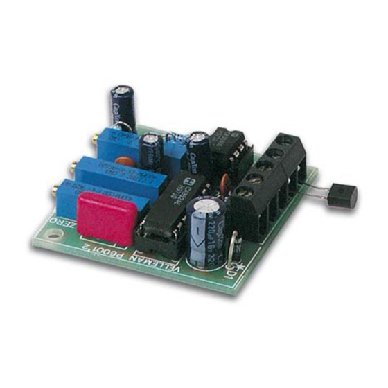
- Page 1 Total solder points: 71 Difficulty level: beginner 1 advanced TEMPERATURE SENSOR K6001 ILLUSTRATED ASSEMBLY MANUAL H6001IP-2...
-
Page 3: Specifications
Features & Specifications This kit has been developed especially to be combined with our K6000 or K6002 in order to create a tem- perature regulating and temperature control system. Combined with the K6000 kit, a completely programma- ble thermostat can be assembled. The use of a separate sensor offers the advantage of making the distance between the controller and the sensor irrelevant. - Page 4 Assembly hints 1. Assembly (Skipping this can lead to troubles ! ) Ok, so we have your attention. These hints will help you to make this project successful. Read them carefully. 1.1 Make sure you have the right tools: • A good quality soldering iron (25-40W) with a small tip.
- Page 5 AXIAL COMPONENTS ARE TAPED IN THE CORRECT MOUNTING SEQUENCE ! REMOVE THEM FROM THE TAPE ONE AT A TIME ! You will find the colour code for the resistances and the LEDs in the HALG (general manual) and on our website: http://www.velleman.be/common/service.aspx...
- Page 6 Construction 1. Metal film resistors 3. IC socket. Watch the 5. Metal film resistors position of the notch! R... R... : 18K (1 - 8 - 0 - 2 - 1) IC1 : 8p : 1K8 (1 - 8 - 0 - 1 - 1) IC2 : 16p : 240K (2 - 4 - 0 - 3 - 1) : 3K...
- Page 7 Construction 7. Multiturn trimmers 11. IC’s. Watch the position 9. Terminal block connectors of the notch! RV1 : 1K (OFFSET) J1 : 2p + 3p IC1 : TLV721 or eq. RV2 : 200K (ZERO) IC2 : 3524 or eq. RV3 : 5K (GAIN) 10.
- Page 8 Preparing the sensor 12. Preparing the sensor Cut two 5cm pieces of the supplied copper wire (fig. 1.1). Using a knife, remove the varnish of both pieces of wire over some 3mm from the ends and tin the ends (fig. 1.1) Fig.
- Page 9 Preparing the sensor Cut off a piece of shrinking tube with a length equal to 5cm Slide the shrinking tube over the copper wires and OVER the sensor (fig. 1.4) Fig. 1.4 Heat the shrinking tube using a hair dryer or, better still, using a paint stripper. Connect the transmitter (type KTY11, KTY81-22 or equivalent) with the points SENSOR of the pcb, using a piece of screened wire (+/- 50cm).
- Page 10 Adjustment & use 13. Adjustment & use IMPORTANT : First have the circuit "warmed up" for about 10 minutes before starting adjusting! Connect the transmitter (type KTY11, KTY81-22 or equivalent) with the points SENSOR of the pcb, us- ing a piece of screened wire (+/- 50cm). The polarity is of no importance. Connect a DIGITAL measuring apparatus between the two connection wires of R2 and R7.
- Page 11 Adjustment & use Further adjustment with the controllers such as K6000, K6002 a. o. : Connect the output of the sensor (OUT + and -) with the points IN (+ and -) of the controller (this can be sensor 1 to 4 in the case of K6000) Plunge the transmitter into the melting ice again and adjust the ZERO trimming potentiometer RV2 so that the indication for this sensor indicates 0°C, and wait until the indication remains stable.
- Page 12 Connection 14. Mounting and connecting The pcb is made in such a way that it easily can be built into a standard wall box, on a blind cover plate. Make a hole in the cover plate to pass the sensor (KTY11, KTY81-22 or eq.) through. The sensor shouldn't touch the cover plate.
- Page 13 15. PCB layout.
- Page 14 Diagram 16. Diagram...
- Page 16 VELLEMAN Components NV Legen Heirweg 33 9890 Gavere Belgium Europe www.velleman.be www.velleman-kit.com Modifications and typographical errors reserved © Velleman Components nv. H6001IP - 2004 - ED2 (rev 1) 5 4 1 0 3 2 9 2 9 1 4 9 5...
Need help?
Do you have a question about the K6001 and is the answer not in the manual?
Questions and answers