
Subscribe to Our Youtube Channel
Related Manuals for Velleman K8067


Summary of Contents for Velleman K8067
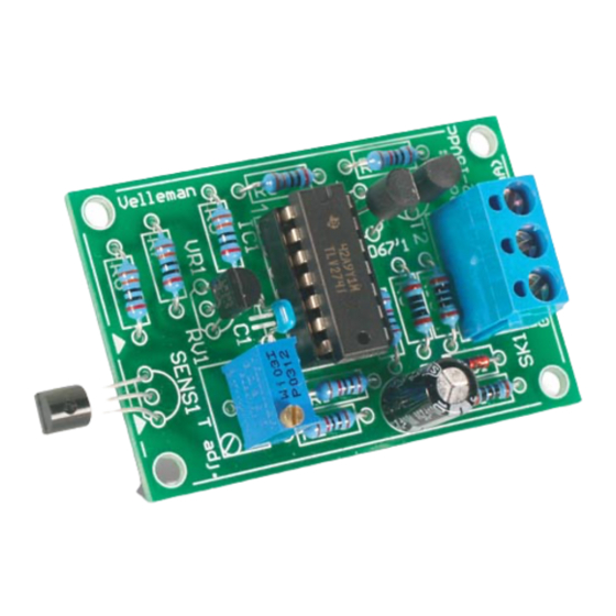
- Page 1 Total solder points: 67 Difficulty level: beginner 1 advanced UNIVERSAL TEMPERATURE SENSOR K8067 ILLUSTRATED ASSEMBLY MANUAL H8067IP-1...
-
Page 3: Specifications
Features & Specifications Features: Small and compact unit. Wide temperature range. One single adjustment. Excellent noise immunity thanks to current loop system. Easily adaptable for 0..5V or 0..10VDC output. Specifications: Temp. range : -20 to +70°C Output : 20mA current loop Max. -
Page 4: Assembly Hints
Assembly hints 1. Assembly (Skipping this can lead to troubles ! ) Ok, so we have your attention. These hints will help you to make this project successful. Read them carefully. 1.1 Make sure you have the right tools: • A good quality soldering iron (25-40W) with a small tip. - Page 5 3- Trim excess leads as close as possible to the solder joint AXIAL COMPONENTS ARE TAPED IN THE CORRECT MOUNTING SEQUENCE ! REMOVE THEM FROM THE TAPE ONE AT A TIME ! You will find the colour code for the resistances and the LEDs on our website: http://www.velleman.be/common/service.aspx...
- Page 6 Construction 1. Zenerdiode. Watch the 3. IC socket, 6. Voltage reference Watch the polarity ! position of the notch ! VR1 : LM385 - 2.5 !!! IC1 : 14P ZD... VR... CATHODE LM335 ZD1 : 12V0 - 500mW 4. Capacitors. 2.
- Page 7 Construction 9. Electrolytic Capacitor Watch the polarity ! C2 : 100µF C ... 10. IC. Watch the position of the notch! IC1 : TLV274 or eq.
- Page 8 Sensor 11. Sensor LM335 The sensor can be placed at a remote location (fig 1.0) instead of on the board (fig 2.0). Max. 1m Fig. 1.0 Fig. 2.0...
- Page 9 Sensor Remote location : Use shielded cable (3.0) and connect the shielding to the ground (sensor pin marked with an arrow on the PCB, see fig 4.0) Shielded cable Fig 4.0 Fig 3.0 shielding Sensor Max. sensor to board distance : 1m Sensor and PCB must be shielded from moisture at all times.
- Page 10 Sensor On board : Follow the steps displayed in figures 6.0 through 6.2 if you want to mount the sensor directly on the PCB. Solder now the connections of the sensor. Solder Fig. 6.0 Fig. 6.1 Fig. 6.2...
- Page 11 Connection 12. Connection to interface card or application: Most applications require 0..5V or 0..10V. Put a resistor between the interface input and ground to convert the current to voltage. To calculate the re- sistor value, divide the max. desired voltage (e.g. 5V) by 0.02. The result is the required resistor value in ohms.
- Page 12 Software 13. Software : Our website ‘www.velleman.be’ features example software written in VB6. Source code is supplied. Use the source code as a guide to write your own applications. The following formula converts the value returned by the AD converter to °C: °C = (101 * AD-value / 256) - 23...
- Page 13 Run your software or the test software. Adjust 'T adj' on the K8067 board until the displayed temperature corresponds with the thermometer indica- tion.
- Page 14 15. PCB layout.
- Page 15 Diagram 16. Diagram (1) Current loop resistor : For 0 to 10V : 500 ohm (V+ = 15V) For 0 to 5V : 250 ohm (V+ = 12V) LM385-2.5 IC1B 100E 200K IC1C BC557 200K IC1A IC1D BC547 200K 0.20mA out (1) 200K R11 100E 100µF/25V...
- Page 16 VELLEMAN Components NV Legen Heirweg 33 9890 Gavere Belgium Europe www.velleman.be www.velleman-kit.com Modifications and typographical errors reserved © Velleman Components nv. H8067IP - 2004 - ED1 (rev.1) 5 4 1 0 3 2 9 3 2 5 9 6 1...
Need help?
Do you have a question about the K8067 and is the answer not in the manual?
Questions and answers