Table of Contents
Advertisement
Quick Links
♦
♦
PRECISION INSTRUMENTS FOR TEST AND MEASUREMENT
1863 and 1864
Megohmmeters
User and Service Manual
Copyright © 2018 IET Labs, Inc.
Visit www.ietlabs.com for manual revision updates
1863-1864 im/Aug 2018
www.ietlabs.com
IET LABS, INC.
Email: info@ietlabs.com
TEL: (516) 334-5959 • FAX: (516) 334-5988
Advertisement
Table of Contents

Related Manuals for iET 1863


Summary of Contents for iET 1863
- Page 1 ♦ ♦ PRECISION INSTRUMENTS FOR TEST AND MEASUREMENT 1863 and 1864 Megohmmeters User and Service Manual Copyright © 2018 IET Labs, Inc. Visit www.ietlabs.com for manual revision updates 1863-1864 im/Aug 2018 www.ietlabs.com IET LABS, INC. Email: info@ietlabs.com TEL: (516) 334-5959 • FAX: (516) 334-5988...
- Page 2 Voltage range on page 4 was 200-230 • Added fuse specs on Aug 2018 • Major update for standardization of marking and required information in the manual www.ietlabs.com IET LABS, INC. Email: info@ietlabs.com TEL: (516) 334-5959 • FAX: (516) 334-5988...
- Page 3 IET specifi cations. If within one year after original shipment, it is found not to meet this standard, it will be repaired or, at the option of IET, replaced at no charge when returned to IET. Changes in this product not approved by IET or application of voltages or currents greater than those allowed by the specifi...
- Page 4 WARNING OBSERVE ALL SAFETY RULES WHEN WORKING WITH HIGH VOLTAGES OR LINE VOLTAGES. Dangerous voltages may be present inside this instrument. Do not open the case Refer servicing to qualifi ed personnel HIGH VOLTAGES MAY BE PRESENT AT THE TERMINALS OF THIS INSTRUMENT WHENEVER HAZARDOUS VOLTAGES (>...
-
Page 5: Table Of Contents
1863 and 1864 Meghommeters Contents Condensed Operating Instructions ............v Safety Summary ..................vi Safety Symbols ..................viiI Specifi cations .....................x Chapter 1: INTRODUCTION ...............1 1.1 Description ....................... 1 1.2 Opening and Tilting the Cabinet ................1 1.3 Controls, Connectors and Indicators ................ 1 1.4 Prefi... - Page 6 4.8 Measurements Under Humid Conditions ..............17 Chapter 5: THEORY ..................19 5.1 Theory Overview ....................19 5.2 Circuit Description ....................19 5.2.1 Type 1863 Megohmmeter ................19 5.2.2 Type 1864 Megohmmeter ................20 Chapter 6: Service And Maintenance ............21 6.1 Service ........................21 6.3 Cabinet Removal ......................
- Page 7 1863 and 1864 Meghommeters Figures Figure 1-1. Type 1864 Front-Panel View ............iv Figure 1-2. Type 1863 Front-panel Controls, Connectors and Indicators ..2 Figure 1-3. Type 1864 rear-panel controls and connectors ......4 Figure 1-4. Methods of connection to the measurement terminals ....5 Figure 2-1.
-
Page 8: Figure 1-1. Type 1864 Front-Panel View
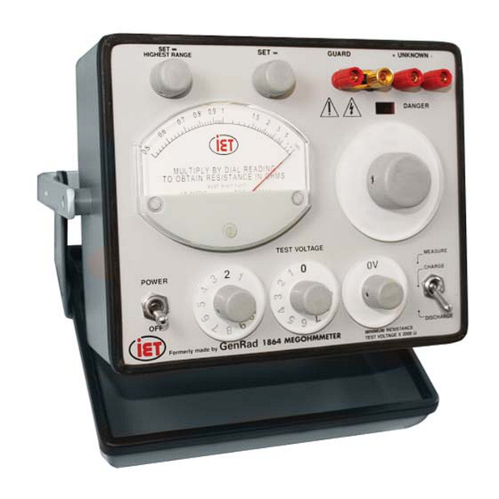
1863 and 1864 Meghommeters ∞ GROUND + UNKNOWN - ∞ GUARD HIGHEST RANGE METER MULTIPLIER DIAL FUNCTION SWITCH POWER-OFF SWITCH TEST-VOLTAGE DIAL Figure 1-1. Type 1864 Front-Panel View NOTE: The 1863 front panel is similar. See Figure 1-2. -
Page 9: Condensed Operating Instructions
Value = Meter reading * Range multiplier 6. For 1863 set the Multiplier dial to 1 M. 12. Set the function switch to DISCHARGE and For 1864 set Multiplier dial to 100 k. -
Page 10: Safety Summary
Voltages of up to 1090 Vdc maybe present at measurement terminals of the 1864 Megohmmeter and voltages of up to 500 Vdc on the measurement terminals of the 1863 Megohmmeter. If an instrument is marked CAT I (IEC Measurement Category I), or it is not marked with a... - Page 11 To avoid the danger of introducing additional hazards, do not install substitute parts or perform unauthorized modifi cations to the instrument. Return the instrument to an IET Labs for service and repair to ensure that safety features are maintained in operational condition.
-
Page 12: Safety Symbols
1863 and 1864 Meghommeters Safety Symbols General defi nitions of safety symbols used on the instrument or in manuals are listed below. Caution symbol: the product is marked with this symbol when it is necessary for the user to refer to the instruction manual. -
Page 13: Specifi Cations
1863 and 1864 Meghommeters Specifi cations 1863 Specifi cations Rmin Rmax (right end) Voltage (Full Scale left end) (10% of scale) (2.5% of scale) Setting ("0.5" rdg) ("5" rdg) ("20" rdg) 50, 100 Vdc 50 kΩ 500 GΩ 2 TΩ... - Page 14 1863 and 1864 Meghommeters Specifi cations Continued Recycling: This product complies with the WEEE Directive (2002/96/EC) marking requirements. The affi xed label indicates that you must not discard this electrical/electronic product in domestic household waste. Product Category: With reference to the equipment types in the WEEE Directive Annex I, this product is classed as a “Monitoring and...
-
Page 15: Chapter 1: Introduction
20 TΩ. The voltage applied to the unknown can be under test. 50, 100, 200, 250 or 500 Vdc when using the 1863. The Type 1864 (Figure 1-2B) indicates resistance 1.2 Opening and Tilting the Cabinet from 50 kΩ... -
Page 16: Figure 1-2. Type 1863 Front-Panel Controls, Connectors And Indicators
1863 and 1864 Meghommeters Figure 1-2. Type 1863 Front-panel Controls, Connectors and Indicators INTRODUCTION... - Page 17 1863 and 1864 Meghommeters Figure 1-2.B Type 1864 Front-panel Controls, Connectors and Indicators INTRODUCTION...
- Page 18 1863 and 1864 Meghommeters INTRODUCTION...
-
Page 19: Figure 1-3. Type 1864 Rear-Panel Controls And Connectors
1863 and 1864 Meghommeters Figure 1-3. Type 1864 rear-panel controls and connectors Table 1.2. Figure 1-3 Name Instrument Type Function Reference 1863 1864 IEC standard Power Input power input Power input and circuit protection receptacle Provides a dc voltage output for recorder or... -
Page 20: Prefi Xes
When several measurements of components with Ω = 10 I GΩ= 10 kΩ= 10 MΩ leads are to be made, consult IET for an appropriate Ω = 10 1 TΩ = 10 kΩ = 10 MΩ= 10 GΩ test jig or fi xture. -
Page 21: Chapter 2: Installation
1863 and 1864 Meghommeters Chapter 2 INSTALLATION Dimensions in inches Figure 2-1. Dimensions of the GR/IET 1863 and 1864 Megohmmeters 2.1 Initial Inspection 2.3 Repackaging for Shipment If the instrument is to be returned to IET Labs, contact IET instruments receive a careful mechanical and the Service Department at the number or address, electrical inspection before shipment. -
Page 22: Storage
fl ammable gasses or fumes. properly connected protection ground. The 1863 and 1864 Megohmmeters are for The 1863 and 1864 Megohmmeters can be operated indoor use only. from either a 100- to 125-V or a 200- to 250-V, 50-to 400-Hz power line. -
Page 23: Figure 2-1. Dimensions Of The Gr/Iet 1863 Megohmmeters
2.10 Cleaning a) The MEAS/CHARGE/DISCHARGE toggle switch is set to DISCHARGE and the red DANGER light To prevent shock unplug the 1863 and 1864 from is OFF. mains prior to cleaning. 7. In the case of an emergency; turn the MEAS/... - Page 24 “Delicate Elec- tronic Instrument”. Please follow online instructions include with RMA # for shipping materials back to IET Labs. Please contact our Sales Department at 516-334-5959, www.ietlabs.com or info@iet- labs.com for technical and additional support.
-
Page 25: Chapter 3: Operation
The 1863 and 1864 should be located on a bench or The current delivered by the megohmmeters under other surface so as not to make the equipment dif- short-circuit conditions is approximately 5 mA. -
Page 26: Operating Guide
(refer to paragraph 4.7). The TEST VOLTAGE dial(s) should be set to the desired measurement voltage. The 1863 Megohm- For best accuracy, keep the leads separated. meter has fi ve individual test voltages, 50, 100, 200, and 500 Vdc. -
Page 27: Measuring An Unknown Value
1863 and 1864 Meghommeters 3.1.5.1 Measuring an Unknown Value 3.1.5.2 Measuring a Known Value When the approximate resistance of the sample to be When the approximate resistance of the sample to be measured is known, proceed as follows: measured is not known, proceed as follows: 1. -
Page 28: Output For Remote Indication
0.5 times the measurement range as the value. Table 3-1 lists the full-scale voltage values for the fi ve test voltages of the 1863. These values are also available on the 1864 along with the other levels that can be set with the variable TEST VOLTAGE switches (see Table 3-1). -
Page 29: Chapter 4: Applications
A com- plete charge-current-vs-time plot will provide more useful information. The Type 1863 and 1864 Megohmmeters can be 4.2 Test Sample Resistivity Measurements used for either true leakage measurements or for measurements at 1-or 10-minute intervals follow- The megohmmeter can be used for measuring the ing the operating procedure described in Section 3. -
Page 30: Capacitor Insulation Resistance
1863 and 1864 Meghommeters Therefore, the time constant is: T = R seconds 5000 where C is in μF. As an example, on the 500 V range, Ro is approximately 100 kΩ so that the time constant for charging of a 1 μF capacitor is 0.1 s. -
Page 31: Discharge Time
(E) must be extremely stable to avoid large time necessary for an indication, assuming an ideal meter fl uctuations. The design of the 1863 and 1864 capacitor, depends on this time constant or that of the is a compromise between these factors. Measurements meter movement, whichever is longer. -
Page 32: Resistance Measurements
GUARD terminal will be a high (negative) voltage level. Often the terminal to be guarded is a large chas- The Types 1863 and 1864 Megohmmeters may be sis and it is, therefore, safer to ground the GUARD used to measure voltage coeffi cient as long as its terminal. -
Page 33: Remote Shielded Measurements
1863 and 1864 Meghommeters 4.7 Remote Shielded Measurements 4.8 Measurements Under Humid Conditions The Types 1863 and 1864 Megohmmeters have been Measurements can be made on components that are some distance from the instrument if care is used to designed to operate under conditions of high humidity... - Page 34 1863 and 1864 Meghommeters This page intentionally left blank. APPLICATIONS...
-
Page 35: Chapter 5: Theory
20-V Zener diode (CR211) to supply voltage effectively multiply the value of the previous standard resistor by a factor of ten. In the 1863 the 200 MΩ levels to run the unity-gain amplifi er (+1). resistor is multiplied to 2 GΩ; in the 1864 the 2 GΩ... -
Page 36: Type 1864 Megohmmeter
HIGHEST RANGE control The circuit of the 1864 Megohmmeter is basically (R241) to the FET amplifi er. the same as that of the 1863 (paragraph 5.2.1). The exceptions are explained in the following paragraphs. A unity-gain FET-input amplifi er (+1) follows the standard resistors in the circuit confi... -
Page 37: Chapter 6: Service And Maintenance
The meter should read 0.5 ± 3%. 6.2 Minimum Performance Standards 14. Increase the voltage to the next higher step (100 on the 1863, 20 V on the 1864). The following checks are provided for verifying the The meter reading should remain at performance of the 1863 and 1864 Megohmmeters. -
Page 38: Figure 6-1. Connections For Measuring Standard Resistors
19. Measure the various standard resistors of the megohmmeter with the DMM according to the settings and tolerances of Table 6.2. Use the IET LOM-510A megohm- meter for resistance values beyond the range of the DMM. SERVICE AND MAINTENANCE... -
Page 39: Cabinet Removal
IEC power input assembly on the rear panel). † This value only appears as a fi xed resistor in the 1864. Since the value is determined by feedback multiplication of the 200-M Ω resistor in the 1863, no measurement should be made with the mogohm bridge. -
Page 40: Calibration
Section 7 will assist in locating components for testing purposes. 6.5 Calibration The accuracy of the 1863 and 1864 depends on the accuracy of the range resistors, the accuracy of the applied voltages and the meter tracking accuracy. -
Page 41: Range-Resistor Accuracy
1. Grasp the knob fi rmly with the fi ngers, close into the panel (or the indicator dial, if ap- Figure 6-2. Top interior view of 1863 Megohmmeter plicable), and pull the knob straight away from the panel. -
Page 42: Knob Installation
1863 and 1864 Meghommeters 6.7 Knob Installation To install a knob assembly on the control shaft: 1. Place the black nylon thrust washer over the control shaft, if appropriate. 2. Mount the bushing on the shaft, using a small slotted piece of wrapping paper as a shim for adequate panel clearance. -
Page 43: Meter Cover Care
= Switch movement to return promptly to a zero reading, once it DS = Lamp = Transformer is deenergized. As supplied by IET, the meter should = Fuse = Integrated Circuit return to zero reading within 30 seconds, immediately = Jack... - Page 44 1863 and 1864 Meghommeters This page intentionally left blank. SERVICE AND MAINTENANCE...
-
Page 45: Chapter 7: Parts Lists And Diagrams
1863 and 1864 Meghommeters Chapter 7 PARTS LISTS AND DIAGRAMS PARTS LISTS AND DIAGRAMS... - Page 46 PARTS LISTS AND DIAGRAMS...
- Page 47 1863 and 1864 Meghommeters PARTS LISTS AND DIAGRAMS...
-
Page 48: Figure 7-1. Replaceable Mechanical Parts On The 1863
Figure 7-1. Replaceable mechanical parts on the 1863 Replaceable parts list for the 1863 Model Ref IET Pt No Description 7910-1300-02 Power switch 5730-1412-01 Meter assembly 5520-5220-AS Knob assembly for 1863/64 potentiometers 3770-2 Red binding post 01-1008-1-0310 Gold binding post... -
Page 49: Figure 7-2. Replaceable Mechanical Parts On The 1864
Figure 7-2. Replaceable mechanical parts on the 1864 Replaceable parts list for the 1864 Model Ref IET Pt No Description 7910-1300-02 Power switch 5730-1412-01 Meter assembly 5520-5220-AS Knob assembly for 1863/64 potentiometers 3770-2 Red binding post 01-1008-1-0310 Gold binding post 1864-1200 Dial assembly 1864-0400 Measure-Charge-Discharge switch 1864-1220... -
Page 50: Figure 7-3. Type 1863 Switching Diagram
Figure 7-3. Type 1863 switching diagram PARTS LISTS AND DIAGRAMS... -
Page 51: Figure 7-4. Regulator And Amplifi Er Circuits Etched-Board Assembly
1863 and 1864 Meghommeters Figure 7-4. Regulator and amplifi er circuits etched-board assembly for 1863 and 1864 Figure 7-5. Type 1863 rectifi er circuit etched-board assembly (P/N 1863-2720) PARTS LISTS AND DIAGRAMS... -
Page 52: Figure 7-6. Type 1863 Schematic Diagram
Figure 7-6. Type 1863 schematic diagram PARTS LISTS AND DIAGRAMS... -
Page 53: Figure 7-7. Type 1864 Switching Diagram
1863 and 1864 Meghommeters PARTS LISTS AND DIAGRAMS... -
Page 54: Figure 7-8. Type 1864 Rectifi Er Circuit Etched-Board Assembly
Figure 7-8. Type 1864 rectifi er circuit etched-board assembly (P/N 1864-2720) PARTS LISTS AND DIAGRAMS... -
Page 55: Figure 7-9. Type 1864 Schematic Diagram
1863 and 1864 Meghommeters PARTS LISTS AND DIAGRAMS... -
Page 56: Figure 7-10. Complete Cabinet Assembly
Figure 7-10. Complete cabinet assembly (P/N 4182-2328) PARTS LISTS AND DIAGRAMS... - Page 57 1863 and 1864 Meghommeters PARTS LISTS AND DIAGRAMS...
- Page 58 PARTS LISTS AND DIAGRAMS...
Need help?
Do you have a question about the 1863 and is the answer not in the manual?
Questions and answers