Sign In
Upload
Manuals
Brands
IET Manuals
Measuring Instruments
1864
IET 1864 Manuals
Manuals and User Guides for IET 1864. We have
1
IET 1864 manual available for free PDF download: User And Service Manual
IET 1864 User And Service Manual (58 pages)
Megohmmeters
Brand:
IET
| Category:
Measuring Instruments
| Size: 5 MB
Table of Contents
Table of Contents
5
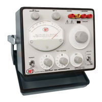
Figure 1-1. Type 1864 Front-Panel View
8
Condensed Operating Instructions
9
Safety Summary
10
Safety Symbols
12
Specifi Cations
13
Chapter 1: INTRODUCTION
15
Description
15
Opening and Tilting the Cabinet
15
Controls, Connectors and Indicators
15
Figure 1-2. Type 1863 Front-Panel Controls, Connectors and Indicators
16
Figure 1-3. Type 1864 Rear-Panel Controls and Connectors
19
Prefi Xes
20
Connections
20
Figure 1-4. Methods of Connection to the Measurement Terminals
20
Chapter 2: INSTALLATION
21
Initial Inspection
21
Dimensions
21
Repackaging for Shipment
21
Storage
22
Bench Setup
22
Rack Mounting
22
Power Connections
22
Figure 2-1. Dimensions of the GR/IET 1863 Megohmmeters
23
Chapter 3: OPERATION
25
Shock Hazard
25
Operating Guide
26
Ground-Link Connection
26
Test Voltage Selection
26
Initial Adjustments
26
Connection of Unknown
26
Measurement Procedure
26
Figure 3-1 Connection to GUARD and +UNKNOWN Terminals
26
Measuring a Known Value
27
Measuring an Unknown Value
27
Output for Remote Indication
28
Chapter 4: APPLICATIONS
29
Insulation Testing
29
Test Sample Resistivity Measurements
29
Capacitor Insulation Resistance
30
General
30
Charging Time Constant
30
Figure 4-1. Electrode Arrangement for Resisitivity Measurements
30
Discharge Time
31
Large Capacitors, very High Resistance
31
Figure 4-2 Basic Megohmmeter Circuit
31
Resistance Measurements
32
Measurement of Voltage Coeffi Cient
32
Guarded 3-Terminal Measurements
32
Figure 4-3. Guarded Measurement of a Three-Terminal Resistor
32
Remote Shielded Measurements
33
Measurements under Humid Conditions
33
Chapter 5: THEORY
35
Theory Overview
35
Circuit Description
35
Type 1863 Megohmmeter
35
Type 1864 Megohmmeter
36
Figure 5-1 Megohmmeter Block Diagram
36
Chapter 6: Service and Maintenance
37
Service
37
Figure 6-1. Connections for Measuring Standard Resistors
38
Cabinet Removal
39
Troubleshooting
39
Calibration
40
Meter Tracking
40
Voltage Accuracy
40
Range-Resistor Accuracy
41
Coarse ∞ Adjustment
41
Knob Removal
41
Figure 6-2. Top Interior View of 1863 Megohmmeter
41
Figure 6-3. Bottom Interior View of 1863 Megohmmeter
41
Knob Installation
42
Figure 6-4. Top Interior View of 1864 Megohmmeter
42
Figure 6-5. Bottom Interior View of 1864 Megohmmeter
42
Meter Cover Care
43
Chapter 7: PARTS LISTS and DIAGRAMS
45
Figure 7-1. Replaceable Mechanical Parts on the 1863
48
Figure 7-2. Replaceable Mechanical Parts on the 1864
49
Figure 7-3. Type 1863 Switching Diagram
50
Figure 7-4. Regulator and Amplifi er Circuits Etched-Board Assembly
51
Figure 7-5. Type 1863 Rectifi er Circuit Etched-Board Assembly
51
Figure 7-6. Type 1863 Schematic Diagram
52
Figure 7-7. Type 1864 Switching Diagram
53
Figure 7-8. Type 1864 Rectifi er Circuit Etched-Board Assembly
54
Figure 7-9. Type 1864 Schematic Diagram
55
Figure 7-10. Complete Cabinet Assembly
56
Advertisement
Advertisement
Related Products
IET 1863
iET 1316
iET 1888
iET 1232-A
iET 1232-AP
iET DE-6000
IET LOM-4000
IET LOM-4001
iET PRS-300 Series
IET Categories
Measuring Instruments
Laboratory Equipment
Amplifier
Test Equipment
Security Sensors
More IET Manuals
Login
Sign In
OR
Sign in with Facebook
Sign in with Google
Upload manual
Upload from disk
Upload from URL