
Related Manuals for iET 1888


Summary of Contents for iET 1888
- Page 1 1888 Megohmmeter/ High Resistance Meter Copyright 2025 IET Labs, Inc. 1888 IM / January 2025...
- Page 2 ...
- Page 3 IET specifi cations. If within one year after original shipment, it is found not to meet this standard, it will be repaired or, at the option of IET, replaced at no charge when returned to IET. Changes in this product not approved by IET or application of voltages or currents greater than those allowed by the specifi...
-
Page 4: Dangerous Procedure Warnings
The 1888 Megohmmeter/High Resistance meter can supply an output voltage as high as 1000Vdc to the external device under test (DUT). Although the 1888 is designed with full attention to operator safety, serious hazards could occur if the instrument is used improperly and these safety instructions are not followed. - Page 5 To avoid the danger of introducing additional hazards, do not install substitute parts or perform unauthorized modifi cations to the instrument. Return the instrument to an IET Labs for service and repair to ensure that safety features are maintained in operational condition.
-
Page 6: Safety Symbols
Safety Symbols General defi nitions of safety symbols used on the instrument or in manuals are listed below. Caution symbol: the product is marked with this symbol when it is necessary for the user to refer to the instruction manual. Hazardous voltage symbol: the product is marked with this symbol when high voltage maybe present on the product and an electrical shock hazard can exist. -
Page 7: Table Of Contents
2.1 Specifi cations .........................3 2.2 General Specifi cations and Stability ................4 2.3 Typical Specifi cations Label ..................5 3.1 Initial Inspection and Features ..................7 3.1.1 Initial Inspection and Accessories ................7 3.1.2 Purpose .........................7 3.1.3 Storage ........................7 3.1.4 Bench and Rack Setup ..................7 3.1.5 Front and Rear Panel ....................8 3.1.6 Power Connections ....................8 3.1.7 Environmental ......................9... - Page 8 5.4 Network Confi guration ....................28 5.5 Web Browser Confi guration ..................29 5.6 VXI Confi guration Utility ....................31 5.7 Resetting Default Network Settings ................33 5.8 1888 Programming .......................33 6.1 Introduction ........................35 6.2 Capabilities ........................35 6.3 Address Switch and Communications Settings ............35 6.4 GPIB Test Keyboard ....................35...
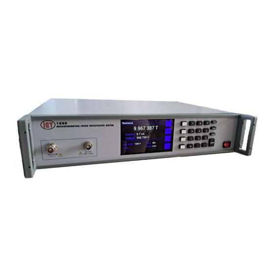
- Page 9 Test fixture. The 1888 can directly display volume resistivity and surface resistivity and The 1888 has a BNC output for the source voltage allows entry of the cell constants and thickness. and triaxial connector for the current detector on the front panel.
- Page 10 Page left intensionally blank...
- Page 11 2.1 Specifi cations Measurement limits: Pass/Fail (1 limit) For convenience to the user, the pertinent specifi cations are given in an Display: Specifi cations Label. Figure 2.1 shows a typical label that is affi xed to Resistance, current, volume resistivity, surface resistivity the case of the instrument.
-
Page 12: General Specifi Cations And Stability
2.2 General Specifi cations and Stability Warm-up: The 1888 should be allowed to stabilize for 15 minutes. The 1888 should be turned on for 1/2 hour for best accuracy. Warm-up the detector for best accuracy. Warm-up can be done by performing a single 60 second measurement at 1000 V with no device connected to the cables. -
Page 13: Typical Specifi Cations Label
2.3 Typical Specifi cations Label A label is affi xed to each 1888 with relevant specifi cations. The typical specifi cations label is shown in Figure 2.1 Resistance range: Short-circuit current: 1 kΩ (10 Ω) to 100 TΩ (10 Ω) <2 mA... - Page 14 Page left intensionally blank...
-
Page 15: Purpose
The 1888 should be placed on a stable fl at work surface. A front bail is provide to make viewing In addition to displaying resistance, the 1888 can easier. -
Page 16: Front And Rear Panel
Power Switch The power cord may of course be selected to match the available receptacle. Confi rm that the power supplied to the 1888 The rear panel, as shown in Figure 3.2, has an meets the following requirements IEC inlet module for connection to mains power,... -
Page 17: Environmental
IEC Inlet Module on the back panel of the 1888. Before operating the instrument inspect the ac power inlet module on the rear of the 1888 UL/CSA type, T 0.8 A,250 V, 5 x 20 mm instrument to ensure that the properly rated fuse is in place. -
Page 18: Interlock Connector
BNC connect can be used as earth/ 3.2.3 Warm-up IMPORTANT chassis ground. The 1888 should be turned on for 1/2 hour for best accuracy. It is also important to warm-up the detector. This can be done by performing a single 60 second measurement at 1000 V with no device connected to the cables. - Page 19 Zeroing Before making measurements, the 1888 1. Turn on the 1888 using the POWER SWITCH instrument should be zeroed to correct for 2. F rom t he H O M E S CRE E N , go to leakage in the test lead or fi xture. The unit MENU>MEASUREMENT SETTINGS...
- Page 21 The two-wire grounded measurement is a type of connection that can be used on the 1888. In a production environment where measurements are repetitive and setup conditions have been The Applied voltage should be limited to 500 previously established, the Range can be fi...
- Page 22 Main Menu>Settings and Utilities...
- Page 23 Main Menu>Continued...
- Page 24 Main Menu>Calibration...
- Page 25 Press MENU to display Main Menu and press the Back key to return to Home screen. Below is the basic menu structure of the 1888. A set of default measurement conditions are initially established at the factory and stored in instrument memory.
-
Page 26: Home Screen
3.8 and shows the calculated resistance in ohms based upon the voltage and current measured. Volume and Surface Resistivity settings are specifi cally designed for use with the 1888-11 Resistivity Cell. The Resistance can also be shown in a Chart and Graph by pressing the CHART button this will show the chart/table display. -
Page 27: Menu Key
Resistance display. Us ing the UP an d DOWN arro w key s The 1888 can be cycled between all 3 displays Measurement Settings can be highlighted during the measurement or once the measurement in yellow, press the ENTER key to go to the is complete. - Page 28 Stopped: Overload occurs anytime current to a mA through 1 nA), which is the maximum current device exceeds 2mA, this would generally mean for the selected range. In auto mode, the 1888 a shorted or very-low-resistance device. instrument will automatically select the optimum...
- Page 29 instrument to auto-range from the 1 mA to 1 µA range (50% of maximum current), or that the user should select the 1µA range based on prior knowledge of the expected results. NOTE When measuring in the current mode, in order to calculate the unknown resistance, the input resistance of the instrument (5 kΩ) must be taken into consideration.
-
Page 30: I/O Settings Menu
1, averaging is disabled, and the display is updated with each measurement. If the value is n (between 2 and 99), the average is displayed Limit: Allows entry of a single measurement after n measurements. If the measure time has limit in scientific units (up to 4 digits with not elapsed after the fi... - Page 31 The Surface Resistivity Cell Constant has Settings menu. a default value of 18.80 1/sq for use with the 1888-11 Resistivity Cell. Accepts entry of a value Highlight the selection and press ENTER to between 0.01 and 400 1/sq. change the selection.
-
Page 32: Utilities Menu
3 seconds for the settings to save. Power- Recall Setup then use the arrow keys to select cycle the 1888 and wait until the main menu is the fi le to be recalled and then press the ENTER shown, for the remote control interface to load, to recall that setup. - Page 33 4.3.1 USB Interface Drivers The USB connection is via a standard USB B Normally when the 1888 is connected to a female connector located on the rear panel. This computer using the USB port, Windows 7 and can be connected to a PC via a standard USB higher will search for the correct driver and as 2.0 A Male to B Male Cable, which is included.
- Page 34 Page left intensionally blank...
-
Page 35: Instrument Calibration Menu
Figure 3.20 - About Menu Figure 3.19 - Change Time/Date Menu 3.5.6 Instrument Calibration Menu The Calibration Menu allows for the adjustment of both measured voltage and measured current . Note that Calibration is only shown in the Menu when the Cal. Enable button is pressed and held. See Chapter 8 for more information on this process. -
Page 36: Environmental Conditions
< 70% RH non-condensing to minimize shifts in resistance. 3.7 Remote Operation When the 1888 is in REMOTE with front panel locked out, a REMOTE indication will be shown in bottom half of the HOME screen. Pressing the LOCAL key will switch the 1888 back to local mode. - Page 37 When using Raw Socket operation fi rst open a similar operating system with RPC calls. The browser and go to the web page for the 1888. VXI-11 specifi cation provides an RPCL (Remote Procedure Call Library) that can be used by...
- Page 38 The VXI-11kybd program This paragraph confi gures the 9006 card in the can be found on the 1888 product page at www. 1888 for operation on your network. The board’s ietlabs.com digital interface is confi...
- Page 39 Figure 5.2 - 9006 Connected to the local hub Ethernet Cables to a hub or switch. Temporarily 2. Apply power to the 1888. Set the Remote local disconnect the local network connection to avoid switch to Remote.
- Page 40 a diff erent range, record the current settings and temporarily set the following network values: Check ‘Use the following IP Address’ IP Address 192.168.1.254 Subnet mask 255.255.255.0 4. Open the browser and enter the default IP address of 192.168.1.254 for new units (or your last set address for older units) in the browser address window.
- Page 41 Vista, 7 and Server 2003 operating systems. The VXI11_confi g.exe program can be found on the 1888 product page at www.ietlabs.com. The VXI11_confi g program can be run from the CD or can be installed onto your hard disk and...
- Page 43 MetCal rather than 488.2 commands. The terminator CRLF should also be used with Met Cal as shown below. To aid the user in operating the 1888, a GPIB 1.001 IEEE CONF:TMEAS 60 [13][10] “Keyboard” Controller program - the easiest...
- Page 44 Listeners key to confirm that the 1888 unit is recognized. Other instruments may also be recognized at this time. Enter and set the Address to the 1888 address. Use the window to send a command string to the 1888, where the command string is con- structed as described in Chapter 7.
- Page 45 Explorer you can now click on scan for instruments. Open NI-MAX, expand devices and interfaces, The 1888 will be found at address 4. select NI GPIB-USB-HS”GPIB0” or GPIB interface being used. When you send a command in NI-Max make sure you send *IDN?\n or CONF:TME?\n.
- Page 46 Page left intensionally blank...
- Page 47 Appendix A and B. The command below sets the 1888 to a voltage For USB, IEEE and LAN <lf>, <cr> or <crlf>, of 250 V and a Measurement Time of 22 seconds.
- Page 48 Page left intensionally blank...
- Page 49 7 resistance values at test. using applied voltages of 1000 V, 500 V and 100 V and comparing the measured resistance values Warm-up IMPORTANT with published specifi cations using the resistance The 1888 should be turned on for 1 hour for best...
- Page 50 Section of this manual. 8.1.4 Adjustment Procedure This Calibration/Adjustment procedure is designed to be performed if the 1888 is found to be out of tolerance or to bring the equipment Figure 8.1 - Calibration Menu closer to published specifi cations.
-
Page 51: Important Note
5 V and reads the voltage back. Remove all cables from Detector and HV Output and power cycle the 1888. If this fi xes the issue the cables are shorted or have a fault. If this does not fi x the issue, it can be due to... - Page 52 Page left intensionally blank...
- Page 53 Model Ref IET Pt No Description 1888 BNC panel mount Panel mount BNC connector part of 1888 Detector board triaxial connector Not Shown 1888 Lemo bulk head Rear bulkhead for interlock Not Shown 1888-Bail-Feet kit 4 x feet and bale kit...
-
Page 55: Program Message
SCPI is an acronym for “Standard Commands for in a common manner. This gives all instruments Programmable Instruments”. For additional in- a common “look and feel”. SCPI commands are formation or an on-line copy of this standard, see: not case-sensitive. http://www.scpiconsortium.org. -
Page 56: Ieee-488.2 Common Commands
Operation complete query Response from the device also returns line feed *WAIT <lf>. Wait until operation is complete before execut- ing next command(No Function in 1888) IEEE-488.2 Common Commands *PCS Note: Commands from Appendix A should not Power-on Status Clear be combined with commands from Appendix B using a semicolon. -
Page 57: Configure:volume
These should be sent as separate lines. For USB, IEEE and LAN <lf>, <cr> or <crlf>, should be used as terminator. The device returns in this case <crlf>. A terminator is required for the 1888 to accept and process a command. CONFIGURE Commands General CONFigure:VOLTage <n>... -
Page 58: Measure Commands
START Initiates a measurement A REM CMD ERR 1 will result if START is sent when the 1888 is already performing a measurement. STOP Stops a measurement in process A REM CMD ERR 1 will result if STOP is sent when the 1888 is already stopped.. -
Page 59: Display Commands
MEASure:ALL? Return the measured resistance/resistivity, current, and voltage value. Units in [ohm, ohm/sq, ohm cm], A, and V. For example for a surface resistivity measurement MEAS:ALL? returns 260.7 Tohm/sq, -0.08 pA, 1.236 DISPLAYCommands DISPlay:TIME <hh:mm> Set the time to hours, minutes. DISPlay:TIME? Queries the time. - Page 60 Sets the IEEE address. <1 to 30> Default is 4 SYSTem:IEEEAddr? Queries the IEEE address. Resets the 1888 as if unit was power cycled. SYSTem:STATus:STRing? Return the current status of the system as a string. When the measurement is in progress, the status replies:“Measurement in process –...
- Page 61 SYSTem:STATus:NUMber? Returns the status as a number When the measurement is in progress: 10 – Run Mode start 11 – Run Mode Charge 12 – Run Mode Measure 13 – Run Mode Discharge 14 – Run Mode Zero When the measurement is complete: 2 –...
- Page 62 16 = Keypad back or keyboard menu 19 = Keypad enter or keyboard enter CALIBRATION Commands Calibration of the 1888 can only be performed manually via the user interface. The calibration coeffi cients can be queried using the following commands when in the calibration menu.
Need help?
Do you have a question about the 1888 and is the answer not in the manual?
Questions and answers