
Related Manuals for PRAXSYM PAMS

Summary of Contents for PRAXSYM PAMS
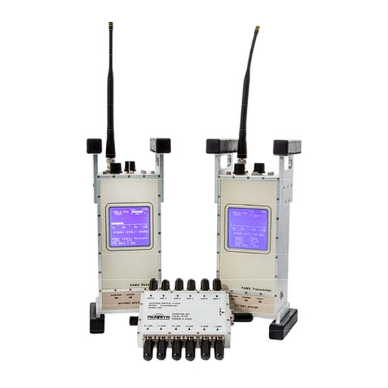
- Page 1 PAMS Portable Attenuation Measurement System User’s Manual The solution for making easy shielding effectiveness measurements. 310-010042-001...
- Page 2 PRAXSYM warrants that all items will be free from defects in material and workmanship under use as specified in this guide for a period of one year from date of delivery. PRAXSYM further agrees to repair or replace, at its discretion, any failure which upon PRAXSYM's inspection appears to be a result of workmanship or material defect.
-
Page 3: Chapter 1 General Information
Chapter 1 General Information Introduction The Portable Attenuation Measurement System (PAMS) is designed to measure the shielding effectiveness of RF enclosures. PAMS is a tool specifically engineered to enable regular maintenance of RF Shielded Enclosures. Routine measurements can be made to ensure a baseline shield level is maintained with minimal disruption to normal activities of the enclosure. - Page 4 PAMS Receiver Specifications Frequency 864-936 MHz Channel Spacing 100 kHz Detection Mode Measurement Range -120dBm to 0 dBm Measurement Accuracy +/-2 dB (-110 to 0 dBm) Frequency Stability +/- 2.5 ppm Charge Voltage at Power Jack DC, 15 +/-1.0 V @ 2A...
- Page 5 P R A X S Y M PAMS Transmitter Specifications Frequency 864-936 MHz Channel Spacing 100 kHz Operating Modes CW, BROADBAND CW Output Power -30 dBm to +30 dB (CW) Broadband Output Combline with pickets at 25 MHz steps from 750 -...
-
Page 6: Chapter 2 System Care
PAMS Transmitter or Receiver. Plug the charger line cord into an AC source (95-250 VAC, 47-63 Hz). The green CHARGE light on the front face of the PAMS unit should illuminate during the entire fast charge cycle. The fast charge cycle of a discharged battery will normally take less than 1.5 hours. -
Page 7: Equipment Service
Slide the battery out of the compartment Storing the PAMS Units If the PAMS units will be stored for long periods between use (2-3 months), it is a good practice to disconnect the batteries to ensure long battery life. With the batteries disconnected, they can be stored charged or discharged. -
Page 8: Chapter 3 Operation
Chapter 3 Operation 3.1 Receiver Receiver Modes The receiver can be operated in one of four different modes. In Shield Level mode the receiver can be used to measure the amount of attenuation/shield level that is provided by an enclosure or other obstacles between the transmitter and receiver. -
Page 9: Set Frequency
Monitor mode is included to emulate the function of the TS-31A system. The TS-31A is the predecessor to PAMS. Monitor mode uses the 12 position RF switch included with the PAMS. It also makes use of up to 12 Ground Plane Antennas which are sold separately. -
Page 10: Control Lock
Initializing Shield Level Measurements In Shield Level mode the signal level measured by the receiver must be initialized to the test signal from the transmitter to indicated 0 dB shield level when the enclosure is open. This initialization process is completed by depressing the CAL button. - Page 11 P R A X S Y M Set the Output Level The transmitter powers up in CW mode with the output level set to - 30 dBm (60 dB attenuation). The output level of the transmitter is adjusted by changing the attenuation level. -30 dBm output level corresponds to 60 dB attenuation and +30 dBm (1 watt) corresponds to 0 dB attenuation.
- Page 12 Control Lock Once set, the controls of the transmitter can be locked to prevent inadvertently changing a setting that could result in measurement errors. Depress the LOCK button on the top of the transmitter to toggle the lock feature on/off. 3.3 Making Shield Level measurements ...
- Page 13 P R A X S Y M With the transmitter and receiver both set to the same test frequency, place the transmitter inside the enclosure on a marked reference position near the center of the enclosure. Ensure the transmitter output level is set to -30 dB. ...
- Page 14 ANT1 – ANT12. Note: The antennas are pre- installed on site and not included in the PAMS. A relative reference level must first be established to be used as a baseline for daily comparison.
- Page 15 Set the transmitter frequency. Connect one end of the calibration cable (supplied with the PAMS set) to the transmitter BNC output and the opposite end to any of the 1x12 switch matrix inputs (labeled ANT1 – ANT12). ...
- Page 16 SHIELDED ROOM - Close Door Begin Test in MONITOR mode Set the switch matrix to select “ANT 1.” Read and manually record the MONIT LEVEL (dB). Repeat the above sequence for antennas 2-12. 12 Position RF Switch Page 15...
- Page 17 P R A X S Y M 3.6 Audio Threshold/Tone Usage Depress the ←/→ THRESHOLD switches until the desired threshold is set. Plug a set of 32 Ω headphones in the jack on the top face of the unit. ...
- Page 18 Notes Page 17...
- Page 19 P R A X S Y M Notes Page 18...
- Page 20 P R A X S Y M 900-000001-001 Rev G...
Need help?
Do you have a question about the PAMS and is the answer not in the manual?
Questions and answers