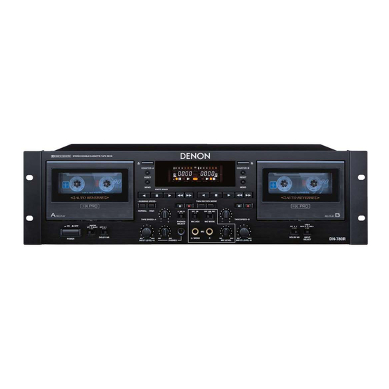
Denon DN-780R Service Manual
Hi-fi component stereo cassette tape deck
Hide thumbs
Also See for DN-780R:
- Operating instructions manual (18 pages) ,
- Operating instructions manual (68 pages)
Table of Contents
Advertisement
Quick Links
Advertisement
Table of Contents

Related Manuals for Denon DN-780R


Summary of Contents for Denon DN-780R
- Page 1 Hi-Fi Component SERVICE MANUAL DN-780R MODEL STEREO CASSETTE TAPE DECK Some illustrations using in this service manual are slightly different from the actual set. 16-11, YUSHIMA 3-CHOME, BUNKYOU-KU, TOKYO 113-0034 JAPAN Telephone: 03 (3837) 5321 X0147 NC 0207...
- Page 2 DN-780R SAFETY PRECAUTIONS The following check should be performed for the continued protection of the customer and service technician. LEAKAGE CURRENT CHECK Before returning the unit to the customer, make sure you make either (1) a leakage current check or (2) a line to chassis resistance check.
- Page 3 DN-780R DISASSEMBLY ( Follow the procedure below in reverse order when reassembling. ) 1. Top Cover (1) From both sides, remove 4 screws , Bracket, and 2 screws (2) Remove 3 screws on the rear, then detach the Top Cover to the arrow direction.
- Page 4 DN-780R 3. DISPLAY P.W.B./VOLUME P.W.B. (1) Pull out 6 knobs on the front. DISPLAY P.W.B. (2) Remove 9 screws on the DISPLAY P.W.B. (3) Remove 2 screws on the MIC UNIT. MIC UNIT knob knob 4. Cassette Mecha. A & B Cassette Mecha.
- Page 5 DN-780R 6. Audio P.W.B. (1) From the Audio P.W.B., disconnect the connector. (2) Remove 3 screws (3) Remove 4 screws " each on the rear. Audio P .W.B. " Connector 7. Power P.W.B. (1) Disconnect the power connector.
- Page 6 DN-780R BLOCK DIAGRAM (Option)
- Page 7 DN-780R LEVEL DIAGRAMS RECORDING SYSTEM INPUT FREQUENCY 400Hz ACD 780 (Option) IC605(606) 7(1) IC707(708) VR804(805) IC108(408) IC110(410) IC103(403) LINE IN HA12170 1(7) 30(1) 16(15) 1(7) VR103(403) IC801(805) IC807 7(1) (dBV) +2.5dB +2.5dB(METAL) +1dB (CHROME) -1dB (NORMAL) -8.2dB -10dB XLR -17.5dB...
- Page 8 DN-780R ACD 780 (Option) LOAD PLAYBACK SYSTEM 600 ohm IC601(603) TCC-130 DOLBY B-TYPE VR101(401) IC101(401) IC104(404) IC105(405) NJM2068 TR101(401) IC103(403) LINE OUT HA12170 1(7) 1(7) 1(7) 3(5) LOAD 33 ohm HEAD PHONE (dBV) +4dB(XLR) 0dB(RCA) -5dB(HEAD PHONE) -10dB -19dB -20dB...
- Page 9 DN-780R ADJUSTMENT ADJUSTING AND CHECKING THE MECHANISM SECTION 1. Replacing Pinch Roller Before replacing the pinch roller, clean the tape contact Capstan shaft surface of the pinch roller and the capstan shaft. Most causes of poor tape transport can be traced to dirty Pinch roller pinch roller and capstan shaft.
- Page 10 DN-780R 5. Checking the Take-up Torque Caution on adjusting Load the cassette type torque meter (1) Before adjusting, clean the head surface, capstan and FWD side ..SONY TW2111A the pinch roller with a gauze or cotton swab moistened REV side ..SONY TW2121A with alcohol.
- Page 11 DN-780R 3. Checking and Adjusting the Tape Speed (1) Connect the frequency counter to the LINE OUT F. Counter terminal and load test tape (SONY TY-224). PB Amp (2) Load cassette tapes on both cassette decks A and B. LINE OUT...
- Page 12 DN-780R 5. Recording System Adjustment REC Amp 5-1. Adjusting recording/playback comprehensive LINE IN frequency characteristics. (1) Load a test tape TDK AC-514. Record with a -20 dB 1 kHz input level signal into PB Amp LINE OUT the LINE IN terminal and playback.
- Page 13 DN-780R MECHANISM OPERATING TIME CHECK The total operating time of the mechanism is registered in this unit. Check and refer to it when replacing the mechanism, head, or motor. 1. Displaying the Operating Time (1) Set the power to on while pressing the “STOP ( )”, “RESET”, and “MEMO” buttons of the Deck A together.
- Page 14 DN-780R SEMICONDUCTORS IC’s MN102L62G (IC105) µ µ µ µ µ COM MN102L62G Terminal Function DET Ext Function Pin Name Symbol Recording selection to B mechanism. P60, WAIT PRECSEL L: Slide switch setup / H: Deck A line in Infrared remote control selection. L: Infrared remote control ...
- Page 15 DN-780R Pin Name Symbol DET Ext Function 38 P37, A15 Reserved Not used. 39 P40, A16 PSCL EEPROM communication clock signal. EEPROM communication data input¾and¾output signal. 40 P41, A17 PSDA (The input port of the time of a power supply injection is carried out.) EEPROM selection signal.
- Page 16 DN-780R MN12510F (IC301) FL DRIVER MN12510F Terminal Function Symbol Function Segment output15 (hi-voltage proof output). LED drive output (hi-voltage proof output). No connection. No connection. Digit output10 (hi-voltage proof output). Digit output9 (hi-voltage proof output). DGT7 Digit output8 (hi-voltage proof output).
- Page 17 DN-780R BA6109U1 (IC101, 102) TC4053BF (IC102, 106, 108, 402, 406, 408, 702~706, 804) V OUT 1 Y-COM X-COM VZ 1 Z-COM F IN FRONT VIEW R IN V OUT 2 HA12170NT (IC103, 403) BA10393F (IC103, 104) X24C00S (IC106) BA15218F (IC104, 105, 107,...
- Page 18 DN-780R TRANSISTORS DTA114EK DTA144EK DTA Series DTC Series DTC114EK VIEW DTC144EK DTA144ES FRONT DTC114ES VIEW DTC124XS DTC143ES DTC114EK 10kohm /W 10kohm /W DTA114EK 10kohm /W 10kohm /W 10kohm /W 10kohm /W DTA144EK 47kohm /W 47kohm /W DTC114ES DTA144ES 47kohm /W...
- Page 19 DN-780R FL DISPLAY BJ881GHK (FL301) COLOR ILLUMINATION Reddish Orange ----- Above pattern part Green ------------------ Other PIN CONNECTION PIN NO. CONNECTION NOTE 1) F1,F2 ---------- Filament 2) NP ------------- No pin 3) NX ------------- No extend pin 4) DL ------------ Datum line...
- Page 20 DN-780R PRINTED WIRING BOARD CONTROL POWER UNIT Ass'y COMPONENT SIDE...
- Page 21 DN-780R CONTROL POWER UNIT Ass'y FOIL SIDE...
- Page 22 DN-780R AUDIO UNIT Ass'y COMPONENT SIDE...
- Page 23 DN-780R AUDIO UNIT Ass'y FOIL SIDE...
- Page 24 DN-780R GU-3463 XLR UNIT Ass'y (ACD-780:Option) COMPONENT SIDE FOIL SIDE...
- Page 25 DN-780R NOTE FOR PARTS LIST Part indicated with the mark " " are not always in stock and possibly to take a long period of time for supplying, or in some case supplying of part may be refused. When ordering of part, clearly indicate "1" and "I" (i) to avoid mis-supplying.
- Page 26 DN-780R PARTS LIST OF P.W.B. UNIT ASS'Y GU-3461 CONTROL POWER UNIT ASS'Y Ref. No. Part No. Part Name Remarks Ref. No. Part No. Part Name Remarks SEMICONDUCTORS GROUP ZD101,102 276 0465 912 HZS7B-2TD ZD103,104 276 0457 904 HZS4C-1TD IC101,102 262 0326 007 BA6109...
- Page 27 DN-780R Ref. No. Part No. Part Name Remarks Ref. No. Part No. Part Name Remarks R209 247 2011 942 RM73B--473JT R854 247 2015 948 RM73B--225KT R210 247 2009 983 RM73B--103JT R855 247 2011 942 RM73B--473JT R211 247 2017 904 RM73B--106KT...
- Page 28 DN-780R Ref. No. Part No. Part Name Remarks Ref. No. Part No. Part Name Remarks Q'ty C801 257 0504 982 CC73CH1H470JT OTHER PARTS GROUP C802 257 0506 951 CC73CH1H101JT CW91 204 2946 007 9P EH-SCN CON.CORD C803,804 254 3068 905 CE04D1H010MBPT(SRA)
- Page 29 DN-780R GU-3462 AUDIO UNIT ASS'Y Ref. No. Part No. Part Name Remarks Ref. No. Part No. Part Name Remarks SEMICONDUCTORS GROUP TR417,418 269 0082 902 DTC114EKT96 TR419-428 269 0088 906 DTC114TKT96 IC101 263 0896 909 NJM2068MD-TE1 TR429,430 273 0460 905 KTC2875B-RTK...
- Page 30 DN-780R Ref. No. Part No. Part Name Remarks Ref. No. Part No. Part Name Remarks R123,124 247 2012 925 RM73B--104JT R253,254 247 2010 927 RM73B--153JT R127,128 247 2012 925 RM73B--104JT R255,256 247 2018 903 RM73B--0R0KT R129,130 247 2009 912 RM73B--512JT...
- Page 31 DN-780R Ref. No. Part No. Part Name Remarks Ref. No. Part No. Part Name Remarks R468 247 2012 925 RM73B--104JT R584 247 2009 983 RM73B--103JT R469,470 247 2010 969 RM73B--223JT R585 247 2018 903 RM73B--0R0KT R471-473 247 2012 925 RM73B--104JT...
- Page 32 DN-780R Ref. No. Part No. Part Name Remarks Ref. No. Part No. Part Name Remarks C157,158 257 0510 905 CK73B1H272KT C425,426 255 1264 953 CQ93M1H272JT(B) C159,160 254 4536 915 CE04W1A470MT SMG/RE3 C427-432 255 1264 940 CQ93M1H222JT(B) C163,164 257 0509 990 CK73B1H222KT...
- Page 33 DN-780R GU-3463 XLR UNIT ASS'Y (ACD-780:Option) Ref. No. Part No. Part Name Remarks Ref. No. Part No. Part Name Remarks C543,544 257 0510 934 CK73B1H472KT SEMICONDUCTORS GROUP C545,546 257 0510 905 CK73B1H272KT IC601-606 263 0565 007 BA15218 C547,548 257 0510 934 CK73B1H472KT...
- Page 34 DN-780R Ref. No. Part No. Part Name Remarks CAPACITORS GROUP C601-604 254 4522 958 CE04W1V101MT SMG/RE3 C605,606 257 0506 951 CC73CH1H101JT C607-610 257 0509 929 CK73B1H102KT C611-614 254 4522 958 CE04W1V101MT SMG/RE3 C615-618 257 0504 940 CC73CH1H330JT C619,620 257 0506 951 CC73CH1H101JT...
- Page 35 DN-780R EXPLODED VIEW OF CABINET WARNING: Parts marked with this symbol have critical characteristics. Use ONLY replacement parts recommended by the manufacturer.
- Page 36 DN-780R Note: The symbols in the column “Remarks” indicate the following destinations. PARTS LIST OF EXPLODED VIEW E2: Europe model E3: U.S.A. & Canada model Ref. No. Part No. Part Name Remarks Q'ty Ref. No. Part No. Part Name Remarks...
- Page 37 DN-780R EXPLODED VIEW OF CASSETTE MECHANISM UNIT (A)
- Page 38 DN-780R PARTS LIST OF CASSETTE MECHANISM (A) UNIT Ref. No. Part No. Part Name Remarks Q'ty 9DF 5170 49 IDLER ASS’Y 9DF 5642 80 REEL MOTOR ASS’Y 9DF 6121 82 CHASSIS BASE ASS’Y 9DF 6230 37 REEL BASE ASS’Y 9DF 6231 27 REEL BASE ASS’Y 7 9DF G156 11A SCREW 2.6X6.0...
- Page 39 DN-780R EXPLODED VIEW OF CASSETTE MECHANISM UNIT (B)
- Page 40 DN-780R PARTS LIST OF CASSETTE MECHANISM (B) UNIT Ref. No. Part No. Part Name Remarks Q'ty 9DF 5170 49 IDLER ASS’Y 9DF 5642 80 REEL MOTOR ASS’Y 9DF 6121 82 CHASSIS BASE ASS’Y 9DF 6230 37 REEL BASE ASS’Y 9DF 6231 27 REEL BASE ASS’Y 7 9DF G156 11A SCREW 2.6X6.4...
- Page 41 DN-780R PACKING VIEW 205 206 213 PARTS LIST OF PACKING & ACCESSORIES Note: The symbols in the column “Remarks” indicate the following destinations. E2: Europe model E3: U.S.A. & Canada model Ref. No. Part No. Part Name Remarks Q'ty 201 513 3809 005 RATING SHEET...
- Page 42 DN-780R WIRING DIAGRAM AC CORD GU-3461-8 ACD 780 (Option) CW091 CY156 15P CX021 CX091 9P GU-3461-3 CX156 15P POWER UNIT CY035 CY033 CY155 15P CX155 15P CX126 12P CY126 12P GU-3462-2 AUDIO UNIT A CX121 12P CY121 12P C.MECHA CX171 17P...
- Page 43 DN-780R SCHEMATIC DIAGRAMS (1/7) WARNING: Parts marked with this symbol have critical characteristics. Use ONLY replacement parts recommended by the manufacture. CAUTION: Before returning the unit to the customer, make sure you make either (1) a leakage current check or (2) a line to chassis resistance check. If the leakage current exceeds 0.5 milliamps, or if the resistance from chassis to either side...
- Page 44 DN-780R SCHEMATIC DIAGRAMS (2/7) B LINE SIGNAL LINE WARNING: Parts marked with this symbol have critical characteristics. Use ONLY replacement parts recommended by the manufacture. CAUTION: Before returning the unit to the customer, make sure you make either (1) a leakage current check or (2) a line to chassis resistance check.
- Page 45 DN-780R SCHEMATIC DIAGRAMS (3/7) WARNING: Parts marked with this symbol have critical characteristics. Use ONLY replacement parts recommended by the manufacture. CAUTION: Before returning the unit to the customer, make sure you make either (1) a leakage current check or (2) a line to chassis resistance check. If the leakage current exceeds 0.5 milliamps, or if the resistance from chassis to either side...
- Page 46 DN-780R SCHEMATIC DIAGRAMS (4/7) WARNING: Parts marked with this symbol have critical characteristics. Use ONLY replacement parts recommended by the manufacture. CAUTION: Before returning the unit to the customer, make sure you make either (1) a leakage current check or (2) a line to chassis resistance check. If the leakage current exceeds 0.5 milliamps, or if the resistance from chassis to either side...
- Page 47 DN-780R SCHEMATIC DIAGRAMS (5/7) WARNING: Parts marked with this symbol have critical characteristics. Use ONLY replacement parts recommended by the manufacture. CAUTION: Before returning the unit to the customer, make sure you make either (1) a leakage current check or (2) a line to chassis resistance check. If the leakage current exceeds 0.5 milliamps, or if the resistance from chassis to either side...
- Page 48 DN-780R SCHEMATIC DIAGRAMS (6/7) WARNING: Parts marked with this symbol have critical characteristics. Use ONLY replacement parts recommended by the manufacture. CAUTION: Before returning the unit to the customer, make sure you make either (1) a NOTICE leakage current check or (2) a line to chassis resistance check. If the leakage ALL RESISTANCE VALUES IN OHM.
- Page 49 DN-780R SCHEMATIC DIAGRAMS (7/7) B LINE SIGNAL LINE NOTICE ALL RESISTANCE VALUES IN OHM. k=1,000 OHM M=1,000,000 OHM ALL CAPACITANCE VALUES IN MICRO FARAD. P=MICRO-MICRO FARAD EACH VOLTAGE AND CURRENT ARE MEASUERD AT MO SIGNAL INPUT CONDITION. CIRCUIT AND PARTS ARE SUBJECT TO CHANGE WITHOUT PRIOR NOTICE.
- Page 50 Ver 1.00 1 page of 30 Specification Serial Interface DN-780R Denon, Ltd.
-
Page 51: Table Of Contents
Ver 1.00 2 page of 30 Contents 1 SERIAL COMMUNICATION INTERFACE................3 1.1 P ......................3 HYSICAL INTERFACE 1.2 T ..................3 RANSFER FORMAT OF SERIAL DATA 1.3 C ................4 OMMAND FORMAT AND ANSWER FORMAT 1.4 P ............4 ROTOCOL FOR DATA TRANSMISSION AND RECEPTION 1.4.1 Basic procedure......................4 1.4.2 Communication errors....................5 1.5 C... -
Page 52: Serial Communication Interface
Ver 1.00 3 page of 30 1 Serial communication interface 1.1 Physical interface Arrangement of connector signals RS-232C Terminal # Signal − − S.GROUND − − − − − 1.2 Transfer format of serial data - Interface :RS-232C - Communication system :Half-duplex communication - Data transfer mode :Start stop synchronization... -
Page 53: Command Format And Answer Format
Ver 1.00 4 page of 30 1.3 Command format and answer format The commands and answers consist of command code (CC) , parameter codes (PC) and some control codes. The commands are transmitted from the host to the device and answers are transmitted from the device to the host. -
Page 54: Communication Errors
Ver 1.00 5 page of 30 g) This device cannot receive any commands for about 1.8seconds after the power switch is turned 1.4.2 Communication errors a) When detect communication error such as overrun, framing, or parity error during receive a command, this device shall give NAK ( 15h ) within 80ms from the start of command transmission . -
Page 55: Command / Answer Sequence
Ver 1.00 6 page of 30 1.5 Command / Answer sequence Shown below are the command sequence and the answer sequence of this device. a) When a command is normally receivedand an answer is normally received with an answer parameter HOST DEVICE Comand Transmitted... - Page 56 Ver 1.00 7 page of 30 b) When a command is abnormally received ( with or without an answer parameter ) HOST UNIT Command Transmitted 40ms 100ms 80ms Error Check NG NAK return Command Retransmitted...
- Page 57 Ver 1.00 8 page of 30 c) When a command with an answer parameter is normally received ( unit ) and an answer is abnormally received ( host ) HOST UNIT Command Transmitted 40ms Error Check OK 40ms 60ms Answer Transmitted Error Check NG 40ms 60ms...
-
Page 58: List Of Command Codes
Ver 1.00 9 page of 30 1.6 List of command codes Here is a list of command code types. :Reset command :Command related to the acquisition of device information ( such as status and name ) :Operation instruction command to the device Command Code(ASCII) Operation... -
Page 59: List Of Answer Codes
Ver 1.00 10 page of 30 1.7 List of answer codes Status Code(ASCII) Description Command OK 20h(SP) Accepts the command. Invalid 30h(0) Invalid command. Format Error 31h(1) Inappropriate command format. CONDITION ERROR 32h(2) Can not process, because of inhibited condition . 1.8 List of status codes Here is a list of answer code types. -
Page 60: Command Specification
Ver 1.00 11 page of 30 1.9 Command specification 1.9.1 Reset When the device received this command, clear all of conditions and restarts same as power ON. byte\bit STX( 02h ) Command code( ‘ SP ‘ ) Reserve( 00h ) Reserve( 00h ) Reserve( 00h ) Reserve( 00h ) -
Page 61: Request Play Status
Ver 1.00 12 page of 30 1.9.2 Request Play Status This command requests the cassette deck playing information. byte\bit STX( 02h ) Command code (‘ 0 ‘) Reserve( 00h ) Reserve( 00h ) Reserve( 00h ) Reserve( 00h ) ETX( 03h ) BCCH( high-level ) BCCL( low-level ) a) Answers returned... -
Page 62: Request Cpu Version
Ver 1.00 13 page of 30 1.9.3 Request CPU Version This command requests the CPU version . byte\bit STX( 02h ) Command code ( ‘ 1 ‘ ) Reserve( 00h ) Reserve( 00h ) Reserve( 00h ) Reserve( 00h ) ETX( 03h ) BCCH( high-level ) BCCL( low-level ) -
Page 63: Request Tape Status
Ver 1.00 14 page of 30 1.1.1 Request Tape Status This command requests condition of the loaded tapes . byte\bit STX( 02h ) Command code ( ‘ 2 ‘ ) Reserve ( 00h ) Reserve ( 00h ) Reserve ( 00h ) Reserve ( 00h ) ETX( 03h ) BCCH( high-level ) -
Page 64: Request Establish
Ver 1.00 15 page of 30 1.9.5 Request Establish This command requests the setup contents (such as switch position and mode select). byte\bit STX( 02h ) Command code ( ‘ 3 ‘ ) Reserve ( 00h ) Reserve ( 00h ) Reserve ( 00h ) Reserve ( 00h ) ETX( 03h ) -
Page 65: Request Machine Id
BCCL( low-level ) a) Answers returned byte\bit STX( 02h ) Reply code ( ‘ 4 ‘ ) Answer code Machine ID 3∼15 “ DENON DN-780R “ (ASCII) ETX( 03h ) BCCH( high-level ) BCCL( low-level ) b) Special conditions - None. -
Page 66: Play
Ver 1.00 17 page of 30 1.9.7 Play The device starts playback when device is not recording related status, and starts recording only from Rec Pause or Rec Mute. Rec Pause means pausing (standby) for record. Rec Mute is muted recording of 5 sec to make time to music record. -
Page 67: Stop
Ver 1.00 18 page of 30 1.9.8 Stop This command stops playback, recording, fast forward and rewind. byte\bit STX( 02h ) Command code (‘ A ‘) Deck mecha ( A Mecha:’ 0 ‘or B Mecha:’ 1 ‘) Reserve ( 00h ) Reserve ( 00h ) Reserve ( 00h ) ETX( 03h ) -
Page 68: Record
Ver 1.00 19 page of 30 1.9.9 This command operations only REC Pause and REC Mute . byte\bit STX( 02h ) Command code (‘ B ‘) Deck mecha ( A Mecha:’ 0 ‘or B Mecha:’ 1 ‘) Reserve ( 00h ) Reserve ( 00h ) Reserve ( 00h ) ETX( 03h ) -
Page 69: Pause
Ver 1.00 20 page of 30 1.9.10 Pause Recording This command pauses recording. byte\bit STX( 02h ) Command code (‘ C ‘) Deck mecha ( A Mecha:’ 0 ‘or B Mecha:’ 1 ‘) Reserve ( 00h ) Reserve ( 00h ) Reserve ( 00h ) ETX( 03h ) BCCH( high-level ) -
Page 70: Forward
Ver 1.00 21 page of 30 1.9.11 Forward The device starts fast forward (right direction of tape). Note that this command’s direction and real sound direction is sometime different. If DIRECTION of Requests Establish is Forward, both directions are same and if REVERSE, the directions are different and this command makes rewind function. -
Page 71: Rewind
Ver 1.00 22 page of 30 1.9.12 Rewind The device starts rewind (left direction of tape). Note that this command’s direction and real sound direction is sometime different. If DIRECTION of Requests Establish is Forward, both directions are same and if REVERSE, the directions are different and this command makes fast forward function. -
Page 72: Direction
Ver 1.00 23 page of 30 1.9.13 Direction This command changes transport direction of the Tape. byte\bit STX( 02h ) Command code (‘ F ‘) Deck mecha ( A Mecha:’ 0 ‘or B Mecha:’ 1 ‘) Reserve (00h) Reserve (00h) Reserve (00h) ETX( 03h ) BCCH( high-level ) -
Page 73: Memory
Ver 1.00 24 page of 30 1.9.14 Memory This selects Memory ON/OFF of counter. byte\bit STX( 02h ) Command code (‘ G ‘) Deck mecha ( A Mecha:’ 0 ‘or B Mecha:’ 1 ‘) ON/OFF ( OFF:’ 0 ‘or ON:’ 1 ‘) Reserve (00h) Reserve (00h) ETX( 03h ) -
Page 74: Counter Reset
Ver 1.00 25 page of 30 1.9.15 Counter reset This resets tape counter. byte\bit STX( 02h ) Command code (‘ H ‘) Deck mecha ( A Mecha:’ 0 ‘or B Mecha:’ 1 ‘) Reserve (00h) Reserve (00h) Reserve (00h) ETX( 03h ) BCCH( high-level ) BCCL( low-level ) a) Answers returned... -
Page 75: Dolby
Ver 1.00 26 page of 30 1.9.16Dolby This selects Dolby NR type. byte\bit STX( 02h ) Command code (‘ I ‘) Deck mecha ( A Mecha:’ 0 ‘or B Mecha:’ 1 ‘) Dolby (*1) Reserve (00h) Reserve (00h) ETX( 03h ) BCCH( high-level ) BCCH ( low-level ) ( *1) Dolby... -
Page 76: Twin Record
Ver 1.00 27 page of 30 1.9.17 Twin REC This prepares Twin REC. byte\bit STX( 02h ) Command code (‘ J ‘) Reserve (00h) Reserve (00h) Reserve (00h) Reserve (00h) ETX( 03h ) BCCH( high-level ) BCCH ( low-level ) a) Answers returned byte\bit STX( 02h ) -
Page 77: Dubbing
Ver 1.00 28 page of 30 1.9.18 Dubbing This starts dubbing. byte\bit STX( 02h ) Command code (‘ K ‘) Tape speed (*1) Reserve (00h) Reserve (00h) Reserve (00h) ETX( 03h ) BCCH( high-level ) BCCH ( low-level ) ( *1) Tape speed Code Tape speed 30h (0) -
Page 78: Speed
Ver 1.00 29 page of 30 1.9.19 Speed This selects tape speed of Twin REC. byte\bit STX( 02h ) Command code (‘ L ‘) Tape speed (*1) Reserve (00h) Reserve (00h) Reserve (00h) ETX( 03h ) BCCH( high-level ) BCCH ( low-level ) ( *1) Tape speed Code Tape speed... -
Page 79: Setting
Ver 1.00 30 page of 30 1.19.20 Setting This sets Reverse mode. byte\bit STX( 02h ) Command code (‘ M ‘) Reverse mode (*1) Reserve (00h) Reserve (00h) Reserve (00h) ETX( 03h ) BCCH( high-level ) BCCH ( low-level ) ( *1) Reverse mode Code Reverse mode...
Need help?
Do you have a question about the DN-780R and is the answer not in the manual?
Questions and answers