Advertisement
Table of Contents
- 1 Safety Precautions
- 2 Top Cover
- 3 Front Panel
- 4 Service Program
- 5 Adjusting the Electrical Sections
- 6 Level Diagrams
- 7 Block Diagram
- 8 Front View
- 9 Top View
- 10 Printed Wiring Board
- 11 Note for Parts List
- 12 Tape Speed
- 13 Wiring Diagram
- 14 Packing View
- 15 Parts List of Packing & Accessories
- Download this manual
For U.S.A., Canada & Europe model
SERVICE MANUAL
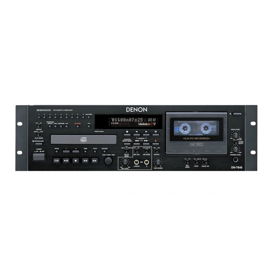
DN-T645/625
MODEL
CD/CASSETTE COMBI-DECK
(This illustration shows the DN-T645 model.)
1 Some illustrations using in this service manual are slightly different from the actual set.
16-11, YUSHIMA 3-CHOME, BUNKYOU-KU, TOKYO 113-0034 JAPAN
Telephone: 03 (3837) 5321
X-0159 NC 0210
Advertisement
Table of Contents

Related Manuals for Denon DN-T645


Summary of Contents for Denon DN-T645
- Page 1 SERVICE MANUAL DN-T645/625 MODEL CD/CASSETTE COMBI-DECK (This illustration shows the DN-T645 model.) 1 Some illustrations using in this service manual are slightly different from the actual set. 16-11, YUSHIMA 3-CHOME, BUNKYOU-KU, TOKYO 113-0034 JAPAN Telephone: 03 (3837) 5321 X-0159 NC 0210...
-
Page 2: Safety Precautions
DN-T645/625 SAFETY PRECAUTIONS The following check should be performed for the continued protection of the customer and service technician. LEAKAGE CURRENT CHECK Before returning the unit to the customer, make sure you make either (1) a leakage current check or (2) a line to chassis resistance check. -
Page 3: Top Cover
DN-T645/625 DISASSEMBLY (To reassemble, reverse disassembly) 1. TOP COVER Remove 6 screws on both sides, and 3 screws on the rear panel. Pull the Top Cover as shown by the arrow direction. 2. FRONT PANEL Turn the unit power on, and open Tray of the CD Mecha. - Page 4 DN-T645/625 Method of opening the Tray when the power would not be turned on in trouble. Please be sure to unplug the cord. Push the lever indicated in the circled figure below with small bar like a pencil or a ball pointed pen, through the square opening on the left side of the main chassis.
- Page 5 DN-T645/625 3. DISPLAY & SW UNIT / KEY UNIT / SW UNIT / MIC UNIT / H/P UNIT / VOLUME UNIT / POWER SW UNIT Pull out 6 knobs on the front. Remove 15 screws and 6 screws on the DISPLAY & KEY UNIT.
- Page 6 DN-T645/625 5. CASSETTE DOOR Take off the Cassette Window on the front. Remove the screw to detach the Mini-damper. Remove the screw to detach the Door Bracket. With pushing the shaft in the arrow directions, no spring side first, detach the Cassette Door.
- Page 7 DN-T645/625 7. XLR UNIT / DECK AMP UNIT Disconnect the connectors from the DECK AMP UNIT. Disconnect the FFC and 2 connectors from the MAIN UNIT. Remove 12 screw, then detach the XLR UNIT to the arrow direction. Remove 3 screws, then detach the DECK AMP UNIT to the arrow direction.
- Page 8 DN-T645/625 9. TRANS UNIT Disconnect the power connector. Remove 4 screws, then detach the TRANS UNIT to the arrow direction.
-
Page 9: Service Program
DN-T645/625 SERVICE PROGRAM Required Measuring Implement Reference disc (TCD784 or CO-74176) 1. What is Service Program Service program is a special program intended for confirming servo functions etc. 2. µcom Version Check Refer to "Preset Functions and Operations" of the instruction manual. - Page 10 DN-T645/625 6. Test Mode (Heat Run mode) Switch on the power while pushing the 3 button and 4 button at the same time. "000TroHR0000" is displayed. And the tray is opened. (1)Hold the disc by the edges and place it on the disc tray.
- Page 11 DN-T645/625 µCOM VERSION UPGRADE System µcom can be upgraded in the following manner. Version Upgrade Method 1.Record the version upgrade software on a CD-R or CD-RW disc, only as one file with the format ISO9660 Mode-1. The file name of the supplied version upgrade software should be used as is and this disc needs to finalize.
- Page 12 DN-T645/625 ADJUSTMENT ADJUSTING AND CHECKING THE MECHANISM SECTION 1. Replacing Pinch Roller Before replacing the pinch roller, clean the tape contact Capstan shaft surface of the pinch roller and the capstan shaft. Most causes of poor tape transport can be traced to dirty Pinch roller pinch roller and capstan shaft.
-
Page 13: Adjusting The Electrical Sections
DN-T645/625 5. Checking the Take-up Torque Caution on adjusting Load the cassette type torque meter (1) Before adjusting, clean the head surface, capstan and FWD side ..SONY TW2111A the pinch roller with a gauze or cotton swab moistened REV side ..SONY TW2121A with alcohol. - Page 14 DN-T645/625 3. Checking and Adjusting the Tape Speed (1) Connect the frequency counter to the LINE OUT F. Counter terminal and load test tape (SONY TY-224). PB Amp (2) Load cassette tapes and playback test tape. LINE OUT (3) At about halfway through the tape, where the tape transport is stable, adjust the VR-502.
- Page 15 DN-T645/625 5. Recording System Adjustment REC Amp 5-1. Adjusting recording/playback comprehensive LINE IN frequency characteristics. (1) Load a test tape TDK AC-514. Record with a -20 dB 1 kHz input level signal into PB Amp LINE OUT the LINE IN terminal and playback.
-
Page 16: Level Diagrams
DN-T645/625 LEVEL DIAGRAMS (1/2) - Page 17 DN-T645/625 LEVEL DIAGRAMS (2/2)
-
Page 18: Block Diagram
DN-T645/625 BLOCK DIAGRAM... - Page 19 DN-T645/625 SEMICONDUCTORS IC’s MN102H60KDA (IC101) MN102H60KDA Terminal Function Pin Name Symbol Function P60, WAIT, SBT2 PCDMUTE Mute for CD P61, _RE Hi-Z Read signal P62, _WEL _WEL Hi-Z Write signal P63, _WE, _WEH PEXTIN Hi-Z EXT.IN signal _CS0,TM13OA _CS0 Hi-Z...
- Page 20 DN-T645/625 Pin Name Symbol Function P33,A11,_KI3 Unfix Address bus AVDD AVDD Analog power supply terminal P34,A12,_KI4 Unfix Address bus P35,A13,_KI5 Unfix Address bus P36,A14,_KI6 Unfix Address bus P37,A15,_KI7 Unfix Address bus P40,A16 Unfix Address bus P41,A17 Unfix Address bus P42,A18...
- Page 21 DN-T645/625 Pin Name Symbol Function _RST _RESET Reset signal 'L': RESET Power supply (+3.3V) P00,D00,AD00 Hi-Z Data bus P01,D01,AD01 Hi-Z Data bus P02,D02,AD02 Hi-Z Data bus P03,D03,AD03 Hi-Z Data bus P04,D04,AD04 Hi-Z Data bus P05,D05,AD05 Hi-Z Data bus P06,D06,AD06 Hi-Z...
- Page 22 DN-T645/625 MN6627911AC (IC201) MN6627911AC Terminal Function Pin No. Pin Name Function DRVDD Power supply for DRAM interface (Pin No.2 - 18, 80) Data I/O signal 0 for DRAM Data I/O signal 1 for DRAM Write enable signal for DRAM RAS control signal for DRAM...
- Page 23 DN-T645/625 Pin No. Pin Name Function DSLF Loop filter for DSL RFSW Loop filter for DSL PLLF Loop filter for PLL PLLFO Loop filter for PLL AVDD2 Power supply for analog (DSL, PLL, AD) AVSS2 GND for analog (DSL, PLL, AD)
- Page 24 DN-T645/625 AN8785SB (IC202) L: All mute [ Others ] Hiz: ch2,4 ON [ Loading ] [ Traverse ] [ Spindle ] [ Focus ] [ Tracking ] H: Active Standby PVcc2 PVcc3 PVcc1 Protection Circuit Standby Band-gap Vcc/Vref Reser Circuit 1.25V...
- Page 25 DN-T645/625 PCM 1716E (IC206) NAME DESCRIPTION LRCIN Left and Right Clock Input. This clock is equal to the sampling rate - f LRCIN ML/IIS Serial Audio Data Input BCKIN Bit Clock Input for Serial Audio Data. MC/DM1 CLKO Buffered Output of Oscillator. Equivalent to...
- Page 26 DN-T645/625 M66005FP (IC701) D I G D I G D I G D I G D I G D I G D i s p l a y C o d e R e g i s t e r...
-
Page 27: Front View
DN-T645/625 BA6109 (IC501) 16M DRAM (IC204) I/O1 I/O4 V OUT1 I/O2 I/O3 F IN FRONT VIEW R IN Vcc1 Vcc2 V OUT2 4M FLASH MEMORY (IC111) TC4053BF (IC306, 308, 312, 313, 318, 320, 654) NJM2068MV (IC301) 4 3 2 1 32 31 30... - Page 28 DN-T645/625 TC74HCT7007AF (IC109, 112) SN74LV541APW (IC104, 106) TC9246F (IC114) Lock Ditection Microcomputer Interface Circuit Programmable Counter Phase Selector Comparator SN74LV573APW (IC103, 105) SN74LV244APW (IC116) AN80L18RMS (IC205) SN75LBC180DR (IC117) MAX3221CAE (IC110) S-24C01B (IC108) Terminal Function FORCEOFF Name Pin No. Function TEST/WP...
- Page 29 DN-T645/625 FL DISPLAY BJ896GN (FL701) 2-1 3-1 4-1 5-1 [1G~11G] [13G] Pin connection Pin No. Connection Pin No. Connection Anode connection NOTE 1) F1,F2 : Filament 2) NP : No pin 1G~10G 3) NC : No connection 4) DL : Datum Line...
-
Page 30: Top View
DN-T645/625 1 TRANSISTORS DTA114EK DTA144EK DTA Series DTC Series DTC114EK VIEW DTC144EK DTC114TK DTA144ES FRONT DTC114ES VIEW DTC123JS 10kohm 10kohm 10kohm 10kohm DTC114EK DTA114EK DTC124XS 10kohm 10kohm DTA144EK 47kohm 47kohm DTC114ES DTC143TS DTA144ES 47kohm 47kohm DTC114TK 10kohm DTC123JS 2.2kohm 47kohm 4.7kohm... -
Page 31: Printed Wiring Board
DN-T645/625 PRINTED WIRING BOARD GU-3478 AUDIO P.W.B. UNIT Ass'y Parts List for DN-T645 Parts List for DN-T625 COMPONENT SIDE... - Page 32 DN-T645/625 Parts List for DN-T645 Parts List for DN-T625 FOIL SIDE...
- Page 33 DN-T645/625 GU-3479 CD P.W.B. UNIT Ass'y Parts List for DN-T645 Parts List for DN-T625 COMPONENT SIDE...
- Page 34 DN-T645/625 Parts List for DN-T645 Parts List for DN-T625 FOIL SIDE...
-
Page 35: Note For Parts List
DN-T645/625 NOTE FOR PARTS LIST Part indicated with the mark " " are not always in stock and possibly to take a long period of time for supplying, or in some case supplying of part may be refused. When ordering of part, clearly indicate "1" and "I" (i) to avoid mis-supplying. - Page 36 DN-T645/625 PARTS LIST OF P.W.B. UNIT for DN-T645 Note: The symbols in the column "Remarks" indicate the following destinations. E3: U.S.A./Canada model E2: Europe GU-3478 AUDIO P.W.B. UNIT ASS'Y Ref.No. Part No. Part Name Remarks SEMICONDUCTORS GROUP IC301 263 1181 901...
- Page 37 DN-T645/625 Ref.No. Part No. Part Name Remarks TR601,602 274 0160 907 2SD2144STPU TR801-808 273 0460 905 KTC2875B-RTK D103-105 276 0717 903 1SS355 TE-17 D301,302 276 0717 903 1SS355 TE-17 D303 276 0704 903 1SR35-400A(T93X) D304-310 276 0717 903 1SS355 TE-17...
- Page 38 DN-T645/625 Ref.No. Part No. Part Name Remarks R399,400 247 2010 998 RM73B--303JT R401,402 247 2008 955 RM73B--302JT R403,404 247 2006 928 RM73B--301JT R405,406 247 2005 945 RM73B--151JT R407,408 247 2006 944 RM73B--391JT R409,410 247 2009 983 RM73B--103JT R411,412 247 2010 985...
- Page 39 DN-T645/625 Ref.No. Part No. Part Name Remarks R514,515 247 2009 983 RM73B--103JT R516 247 2011 971 RM73B--623JT R517,518 247 2008 968 RM73B--332JT R519,520 247 2009 909 RM73B--472JT (1608) R521,522 247 2009 967 RM73B--822JT R523,524 247 2009 983 RM73B--103JT R525,526 247 2010 956...
- Page 40 DN-T645/625 Ref.No. Part No. Part Name Remarks R827,828 247 2013 937 RM73B--304JT R829-832 247 2010 956 RM73B--203JT R833-836 247 2004 920 RM73B--470JT R837,838 247 2011 997 RM73B--753JT R839-842 247 2012 967 RM73B--154JT R843,844 247 2012 925 RM73B--104JT R845,846 247 2012 967...
- Page 41 DN-T645/625 Ref.No. Part No. Part Name Remarks C393,394 257 0510 963 CK73B1H822KT C395,396 257 0506 993 CC73CH1H151JT C397,398 257 0504 982 CC73CH1H470JT C401,402 254 4536 915 CE04W1A470MT SMG/RE3 C403,404 254 4524 943 CE04W1H010MT SMG/RE3 C406,407 254 4538 900 CE04W1C100MT SMG/RE3...
- Page 42 DN-T645/625 Ref.No. Part No. Part Name Remarks C811-814 254 4522 958 CE04W1V101MT SMG/RE3 C815,816 257 0503 970 CC73CH1H160JT C817,818 257 0503 909 CC73CH1H8R0DT C819-822 257 0509 929 CK73B1H102KT C823-826 254 4522 958 CE04W1V101MT SMG/RE3 C827,828 257 0503 970 CC73CH1H160JT C829,830...
- Page 43 DN-T645/625 Ref.No. Part No. Part Name Remarks S771,772 212 1167 008 SLIDE SWITCH S773 212 0417 005 SLIDE SWITCH(1-3) S801 212 1147 002 SLIDE SW S802 212 1154 008 SLIDE SWITCH S981 212 1030 009 POWER SWITCH (TV-5) ST301 205 0452 017...
- Page 44 SN74LV02APW-EL2 IC108 262 3114 902 S-24C01BFJ-TB IC109 262 2376 903 TC74HCT7007AF(TP1) IC110 262 3172 902 MAX3221CAE-T IC111 GEN6288 SYSTEM ROM for DN-T645 4M FLASH IC112 262 2376 903 TC74HCT7007AF(TP1) IC113 262 2651 903 BU2618FV(E2) IC114 262 1883 905 TC9246F-TP1 IC116...
- Page 45 DN-T645/625 Ref.No. Part No. Part Name Remarks TR509-511 269 0054 901 DTC144EKT96 TR651,652 275 0042 905 2SK373(Y)TPE2 TR653-656 273 0460 905 KTC2875B-RTK TR901 272 0025 907 2SB562(C)TF D101 276 0773 905 RB501V-40 D102 276 0717 903 1SS355 TE-17 D106-109 276 0717 903...
- Page 46 DN-T645/625 Ref.No. Part No. Part Name Remarks R173,174 247 2012 925 RM73B--104JT R175 247 2012 912 RM73B--913JT R176 247 2012 983 RM73B--184JT R177 247 2005 903 RM73B--101JT R178 247 2013 937 RM73B--304JT R179 247 2008 939 RM73B--242JT R180 247 2009 912...
- Page 47 DN-T645/625 Ref.No. Part No. Part Name Remarks R267-274 247 2009 983 RM73B--103JT R275 247 2010 956 RM73B--203JT R276 247 2006 960 RM73B--471JT R277 247 2014 965 RM73B--105JT R278 247 2004 975 RM73B--750JT R282 247 2009 925 RM73B--562JT R283 247 2010 901...
- Page 48 DN-T645/625 Ref.No. Part No. Part Name Remarks R545,546 247 2009 983 RM73B--103JT R547 247 2008 955 RM73B--302JT R548 247 2009 912 RM73B--512JT R641-644 247 2009 983 RM73B--103JT R645-648 247 2004 920 RM73B--470JT R651,652 247 2008 939 RM73B--242JT R655,656 247 2014 965...
- Page 49 DN-T645/625 Ref.No. Part No. Part Name Remarks C107 254 4533 921 CE04W0J101MT SMG/RE3 C108,109 257 0512 903 CK73F1E104ZT C110 254 4533 921 CE04W0J101MT SMG/RE3 C111 257 0512 903 CK73F1E104ZT C112 257 0511 904 CK73F1H103ZT C113 257 0512 903 CK73F1E104ZT C114...
- Page 50 DN-T645/625 Ref.No. Part No. Part Name Remarks C209 257 0512 903 CK73F1E104ZT C210 254 4533 934 CE04W0J221MT SMG/RE3 C211-214 257 0512 903 CK73F1E104ZT C217-220 257 0509 990 CK73B1H222KT C221 254 4538 900 CE04W1C100MT SMG/RE3 C222,223 257 0516 909 CK73B1E223KT C224...
- Page 51 DN-T645/625 Ref.No. Part No. Part Name Remarks C502 254 4541 955 CE04W1E221MT SMG/RE3 C503 257 0501 901 CK73B1H103KT (1608) C504 257 0509 929 CK73B1H102KT C505 254 4524 943 CE04W1H010MT SMG/RE3 C506 254 4522 903 CE04W1V4R7MT SMG/RE3 C507-510 257 0509 929...
- Page 52 DN-T645/625 Ref.No. Part No. Part Name Remarks CY071 205 0321 070 7P CONNE BASE(RED) CY082 205 1228 004 8P FJ CONN.BASE CY091 205 0885 037 9P CON.SOCKET TUC-P CY191 205 0736 018 19P FFC CON.BASE F981 206 1087 044 FUSE (ET0.5A)
- Page 53 DN-T645/625 PARTS LIST OF P.W.B. UNIT for DN-T625 Note: The symbols in the column "Remarks" indicate the following destinations. E3: U.S.A./Canada model E2: Europe model GU-3478A AUDIO P.W.B. UNIT ASS'Y Ref.No. Part No. Part Name Remarks SEMICONDUCTORS GROUP IC301 263 1181 901...
- Page 54 DN-T645/625 Ref.No. Part No. Part Name Remarks TR587 273 0456 906 2SC5395-T12-E/F TR589 269 0082 902 DTC114EKT96 TR601,602 274 0160 907 2SD2144STPU TR801-808 273 0460 905 KTC2875B-RTK D103-105 276 0717 903 1SS355 TE-17 D301,302 276 0717 903 1SS355 TE-17 D303...
- Page 55 DN-T645/625 Ref.No. Part No. Part Name Remarks R393,394 247 2008 997 RM73B--432JT R395,396 247 2007 943 RM73B--102JT R397,398 247 2012 983 RM73B--184JT R399,400 247 2010 998 RM73B--303JT R401,402 247 2008 955 RM73B--302JT R403,404 247 2006 928 RM73B--301JT R405,406 247 2005 945...
- Page 56 DN-T645/625 Ref.No. Part No. Part Name Remarks R514,515 247 2009 983 RM73B--103JT R516 247 2011 971 RM73B--623JT R517,518 247 2008 968 RM73B--332JT R519,520 247 2009 909 RM73B--472JT (1608) R521,522 247 2009 967 RM73B--822JT R523,524 247 2009 983 RM73B--103JT R527,528 247 2009 912...
- Page 57 DN-T645/625 Ref.No. Part No. Part Name Remarks R853-856 247 2004 920 RM73B--470JT R857,858 247 2005 945 RM73B--151JT R859,860 247 2010 956 RM73B--203JT R861,862 247 2005 945 RM73B--151JT R863,864 247 2010 956 RM73B--203JT R865-868 247 2018 903 RM73B--0R0KT R869-872 247 2005 945...
- Page 58 DN-T645/625 Ref.No. Part No. Part Name Remarks C419-422 257 0506 993 CC73CH1H151JT C423,424 254 4538 900 CE04W1C100MT SMG/RE3 C425,426 254 4524 956 CE04W1H2R2MT SMG/RE3 C427,428 254 4538 900 CE04W1C100MT SMG/RE3 C429,430 254 4524 930 CE04W1HR47MT SMG/RE3 C431,432 254 4536 915...
- Page 59 DN-T645/625 Ref.No. Part No. Part Name Remarks CX035 205 0133 035 3P NH CONNECTOR BASE CX061 205 0321 067 6P CONNE.BASE (RED) CX082 205 1229 003 8P FJ CONN.PLUG CX101 205 0375 000 10P CON.BASE(KR-PH) CX121 205 0535 028 12P CONNE BASE...
- Page 60 DN-T645/625 GU-3479A/3479D CD P.W.B. UNIT ASS'Y Ref.No. Part No. Part Name Remarks SEMICONDUCTORS GROUP IC101 262 3171 000 MN102H60KDA IC103 262 2642 909 SN74LV573APW-EL2 IC104 262 2641 900 SN74LV541APW-EL2 IC105 262 2642 909 SN74LV573APW-EL2 IC106 262 2641 900 SN74LV541APW-EL2 IC107...
- Page 61 DN-T645/625 Ref.No. Part No. Part Name Remarks D106-109 276 0717 903 1SS355 TE-17 D501 276 0717 903 1SS355 TE-17 D502 276 0704 903 1SR35-400A(T93X) D506,507 276 0717 903 1SS355 TE-17 D751,752 276 0432 903 1SS270A TE (TAPE) D754-764 276 0432 903...
- Page 62 DN-T645/625 Ref.No. Part No. Part Name Remarks R190,191 247 2003 947 RM73B--220JT R192 247 2010 927 RM73B--153JT R193 247 2014 965 RM73B--105JT R195 247 2005 903 RM73B--101JT R201,202 247 2008 968 RM73B--332JT R203,204 247 2010 972 RM73B--243JT R205 244 2043 937...
- Page 63 DN-T645/625 Ref.No. Part No. Part Name Remarks R294,295 247 2003 989 RM73B--330JT R332,333 247 2009 983 RM73B--103JT R334,335 247 2005 987 RM73B--221JT R336 247 2009 983 RM73B--103JT R340-345 247 2003 989 RM73B--330JT R346,347 247 2011 942 RM73B--473JT R348 247 2009 983...
-
Page 64: Tape Speed
DN-T645/625 Ref.No. Part No. Part Name Remarks VR502 211 6132 941 V06PB223T VR653 211 5647 000 V09Q20FB103K TAPE SPEED CAPACITORS GROUP C101 257 0512 903 CK73F1E104ZT C102 254 4533 921 CE04W0J101MT SMG/RE3 C103 257 0511 904 CK73F1H103ZT C104 257 0512 903... - Page 65 DN-T645/625 Ref.No. Part No. Part Name Remarks C185 257 0511 904 CK73F1H103ZT C186 257 0512 903 CK73F1E104ZT C201 257 0512 903 CK73F1E104ZT C202 257 0509 929 CK73B1H102KT C203 257 0512 903 CK73F1E104ZT C204 257 0509 929 CK73B1H102KT C205 257 0516 909...
- Page 66 DN-T645/625 Ref.No. Part No. Part Name Remarks C284,285 257 0512 903 CK73F1E104ZT C287,288 254 4538 900 CE04W1C100MT SMG/RE3 C289 257 0512 903 CK73F1E104ZT C290 254 4538 900 CE04W1C100MT SMG/RE3 C291,292 257 0512 903 CK73F1E104ZT C293,294 254 4538 955 CE04W1C221MT SMG/RE3...
- Page 67 DN-T645/625 Ref.No. Part No. Part Name Remarks FB101-121 235 0130 903 CHIP EMIFIL(11A121) FB123 235 0130 903 CHIP EMIFIL(11A121) FB125 235 0130 903 CHIP EMIFIL(11A121) FB202-206 235 0130 903 CHIP EMIFIL(11A121) FF981 202 0040 909 FUSE CLIP (TAPE) FH981 202 0040 909...
- Page 68 DN-T645/625 EXPLODED VIEW FOR DN-T645 MODEL WARNING: Parts marked with this symbol have critical Parts List characteristics. Use ONLY replacement parts recommended by the manufacturer. (FRONT PANEL SUB ASS'Y) 17 101...
- Page 69 DN-T645/625 PARTS LIST OF EXPLODED VIEW for DN-T645 model Note: The symbols in the column "Remarks" indicate the following destinations. E3: U.S.A./Canada model E2: Europe model Ref.No. Part No. Part Name Remarks Q'ty GU-3478 AUDIO P.W.B. UNIT ASS'Y DECH AMP UNIT DISPLAY &...
- Page 70 DN-T645/625 Ref.No. Part No. Part Name Remarks Q'ty 002 9032 004 7C R.WIRE ASS(AWG26) 203 0589 036 1P CON ASS'Y (A) 203 5307 019 3P VH-VH CON.CORD 203 6407 028 4P KR-KR CON CORD 393 8066 003 FL TUBE (BJ896GN)
- Page 71 DN-T645/625 Ref.No. Part No. Part Name Remarks Q'ty 473 7007 013 4X10 CBTS (S)-B 477 0263 005 3P. SWELLING SCREW 473 7500 002 3X6 CBTS (P)-Z 475 1189 001 4W (16X4.5X1) BK...
- Page 72 DN-T645/625 EXPLODED VIEW FOR DN-T625 MODEL WARNING: Parts marked with this symbol have critical characteristics. Parts List Use ONLY replacement parts recommended by the manufacturer. (FRONT PANEL SUB ASS'Y) 17 101...
- Page 73 DN-T645/625 PARTS LIST OF EXPLODED VIEW for DN-T625 model Note: The symbols in the column "Remarks" indicate the following destinations. E3: U.S.A./Canada model E2: Europe model Ref.No. Part No. Part Name Remarks Q'ty GU-3478A AUDIO UNIT DECH AMP UNIT DISPLAY & SW UNIT...
- Page 74 DN-T645/625 Ref.No. Part No. Part Name Remarks Q'ty 411 1360 321 CHASSIS 461 0911 006 FOOT SHEET 411 2023 007 MECHA BASE 412 4278 002 TRANS BRACKET 105 1413 027 BACK PANEL for E3 105 1413 030 BACK PANEL for E2...
- Page 75 DN-T645/625 EXPLODED VIEW OF CD MECHANISM UNIT (CD11FTA3N) PARTS LIST OF CD MECHANISM UNIT Ref. No. Part No. Part Name Remarks Q'ty Ref. No. Part No. Part Name Remarks Q'ty 1 964 0009 006 Frame chassis 11 964 0010 008 Mecha lifter...
- Page 76 DN-T645/625 EXPLODED VIEW OF CASSETTE MECHANISM UNIT (A)
- Page 77 DN-T645/625 PARTS LIST OF CASSETTE MECHANISM (A) UNIT Ref. No. Part No. Part Name Remarks Q'ty 9DF 5170 49 IDLER ASS’Y 9DF 5642 80 REEL MOTOR ASS’Y 9DF 6121 82 CHASSIS BASE ASS’Y 9DF 6230 37 REEL BASE ASS’Y 9DF 6231 27 REEL BASE ASS’Y 7 9DF G156 11A SCREW 2.6X6.0...
-
Page 78: Wiring Diagram
DN-T645/625 WIRING DIAGRAM... -
Page 79: Packing View
E2 515 0923 100 S.S.LIST COM.(EX) 203 2360 004 2P PIN CORD 501 2200 013 CARTON CASE for DN-T645 model 501 2200 026 CARTON CASE for DN-T625 model CONT.CARD(L)SUB ASSY BAR CODE LABEL ASS'Y 513 2303 007 VERSION LABEL... - Page 80 DN-T645/625 SCHEMATIC DIAGRAMS (1/6) NOTICE: CAUTION: ± B LINE ALL RESISTANCE VALUES IN OHM. k=1,000 OHM M=1,000,000 OHM Before returning the unit to the customer, make sure you make either (1) a SIGNAL LINE ALL CAPACITANCE VALUES IN MICRO FARAD. P=MICRO-MICRO FARAD leakage current check or (2) a line to chassis resistance check.
- Page 81 DN-T645/625 SCHEMATIC DIAGRAMS (2/6) ± B LINE SIGNAL LINE SCHEMATIC DIAGRAMS (2/6) NOTICE: CAUTION: ALL RESISTANCE VALUES IN OHM. k=1,000 OHM M=1,000,000 OHM GU-3478-1 DECK AMP UNIT(2/2) Before returning the unit to the customer, make sure you make either (1) a ALL CAPACITANCE VALUES IN MICRO FARAD.
- Page 82 DN-T645/625 SCHEMATIC DIAGRAMS (3/6) NOTICE: ALL RESISTANCE VALUES IN OHM. k=1,000 OHM M=1,000,000 OHM ALL CAPACITANCE VALUES IN MICRO FARAD. P=MICRO-MICRO FARAD EACH VOLTAGE AND CURRENT ARE MEASUERD AT NO SIGNAL INPUT CONDITION. ± B LINE CIRCUIT AND PARTS ARE SUBJECT TO CHANGE WITHOUT PRIOR SIGNAL LINE NOTICE.
- Page 83 DN-T645/625 SCHEMATIC DIAGRAMS (4/6) ± B LINE NOTICE: SIGNAL LINE CAUTION: ALL RESISTANCE VALUES IN OHM. k=1,000 OHM M=1,000,000 OHM Before returning the unit to the customer, make sure you make either (1) a ALL CAPACITANCE VALUES IN MICRO FARAD. P=MICRO-MICRO FARAD SCHEMATIC DIAGRAMS (4/6) leakage current check or (2) a line to chassis resistance check.
- Page 84 DN-T645/625 SCHEMATIC DIAGRAMS (5/6) NOTICE: ALL RESISTANCE VALUES IN OHM. k=1,000 OHM M=1,000,000 OHM ALL CAPACITANCE VALUES IN MICRO FARAD. P=MICRO-MICRO FARAD EACH VOLTAGE AND CURRENT ARE MEASUERD AT NO SIGNAL INPUT CONDITION. CIRCUIT AND PARTS ARE SUBJECT TO CHANGE WITHOUT PRIOR NOTICE.
- Page 85 DO NOT return the unit to the customer until the problem is located and corrected. ± B LINE SIGNAL LINE SCHEMATIC DIAGRAMS (6/6) GU-3479-2 MIC UNIT (DN-T645 only) GU-3479-3 TRANS UNIT GU-3479-4 25P DSUB UNIT (DN-T645 only) GU-3479-5 KEY UNIT GU-3479-6 SPEED VOL UNIT (DN-T625 only)
Need help?
Do you have a question about the DN-T645 and is the answer not in the manual?
Questions and answers