
Related Manuals for Clarke CBS1-5


Summary of Contents for Clarke CBS1-5
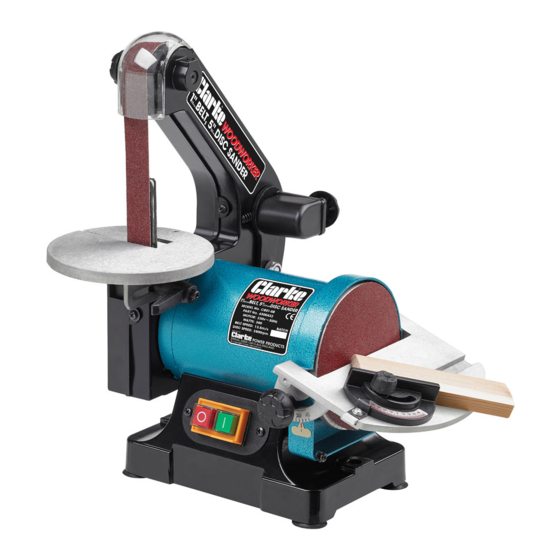
- Page 1 BELT/DISC SANDER BELT/DISC SANDER MODEL NO: CBS1-5 PART No: 6500403 OPERATION & MAINTENANCE INSTRUCTIONS 1004...
- Page 2 Please note that the details and specifications contained herein, are correct at the time of going to print. However, CLARKE International reserve the right to change specifications at any time without prior notice. CLARKE International. Hemnall Street, Epping, Essex CM16 4LG...
- Page 3 Thank you for purchasing this CLARKE Belt and Disk Sander designed for hobby/ DIY, indoor use, and for sanding wood or wood products only. Before attempting to use the sander, please read this manual thoroughly and follow the instructions carefully. In doing so you will ensure the safety of yourself and that of others around you, and you can look forward to the sander giving you long and satisfactory service.
- Page 4 Safety Precautions WARNING: As with all machinery, there are certain hazards involved with their operation and use. Exercising respect and caution will considerably lessen the risk of personal injury. However, if normal safety precautions are overlooked or ignored, personal injury to the operator or damage to property, may result. ALWAYS Learn the machines applications, limitations and the specific potential hazards peculiar to it.
-
Page 5: Cover
14. ALWAYS wear proper apparel. Loose clothing or jewellery may get caught in moving parts. Wear protective hair covering to contain long hair. 15. ALWAYS guard against electric shock. Avoid contact with earthed surfaces..pipes, radiators etc. 16. NEVER operate machine while under the influence of drugs, alcohol or any medication. - Page 6 Electrical Connections Connect the mains lead to a standard, 230 volt (50Hz) electrical supply through a fused good quality 13 amp BS 1363 plug, or a suitable fused isolator switch. WARNING: THIS APPLIANCE MUST BE EARTHED IMPORTANT: The wires in the mains lead are coloured in accordance with the following code: Green &...
-
Page 7: Washer
Unpack the Sander and lay out the components, checking to ensure that no damage was suffered during transit. Any damage should be reported to your Clarke dealer immediately. Loose items are as follows, referring to the illustration above: 1 x Disk Sanding Table... -
Page 8: Screw
Assembly 1. Belt Table • Gently ease the table into place with the belt support entering the slot in the table. • Screw the Table Locking Lever into place, ensuring a flat washer is used on the levers’ threads noting that the locking lever has a LEFT HAND thread, i.e. -
Page 9: Screw
• With the table secured, position the Disk Cover/Dust Extraction Port as shown, with the locating pin on the cover ‘A’, engaged in the slot in the hinged cover ‘B’. • Secure with four screws (arrowed) 3. Feet The four feet may be very gently eased into the holes at the base of the machine. Alternatively, the machine may be mounted on a workbench or a wooden base, using the four holes in the base as mounting holes. -
Page 10: Screw
• It is possible to set the table to any angle up to 45 degrees, simply by slackening the locking lever and positioning the table using a protractor or angle setter, then retightening the locking lever. 2. Disk Table Adjustment •... -
Page 11: Screw
Maintenance IMPORTANT! Whenever making adjustments or carrying out maintenance tasks, ALWAYS switch OFF the machine and disconnect from the power supply. 1. Changing the Sanding Belt 1.1 Remove the belt table completely by unscrewing and removing the table locking lever. 1.2 Remove the two side cover securing screws (9A), followed by the upper roller pivot screw (9B), then pull off the side cover. - Page 12 PARTS LIST & DIAGRAMS WARNING: The use of spare parts, other that those supplied by CLARKE International or one of its recognised dealers, may be hazardous and could invalidate the guarantee.
- Page 13 Parts Diagram...
-
Page 14: Table Of Contents
Parts List Item Description Part No Knob HTCBS1501 Cover HTCBS1502 Label HTCBS1503 Warning Label HTCBS1504 Belt HTCBS1505 Retaining Ring HTCBS1506 Bearing HTCBS1507 Driven Wheel HTCBS1508 Shaft HTCBS1509 Plastic Belt Guard HTCBS1110 Washer HTCBS1111 Screw HTCBS1112 Screw HTCBS1113 Pulley HTCBS1514 Body HTCBS1515 Adjustable Shaft HTCBS1516... - Page 15 Parts List cont. Item Description Part No Spring HTCBS1543 Screw HTCBS1544 SCrew HTCBS1545 Motor HTCBS1546 Screw HTCBS1547 Washer HTCBS1548 Screw HTCBS1549 Washer HTCBS1550 Pointer HTCBS1551 Cover HTCBS1552 Screw HTCBS1553 Disk HTCBS1554 Sanding disk HTCBS1555 Knob HTCBS1556 Washer HTCBS1557 Mitre Gauge HTCBS1558 Screw HTCBS1559...
Need help?
Do you have a question about the CBS1-5 and is the answer not in the manual?
Questions and answers