Table of Contents
Advertisement
Advertisement
Table of Contents

Subscribe to Our Youtube Channel
Related Manuals for Transcell Technology TI-1500B


Summary of Contents for Transcell Technology TI-1500B
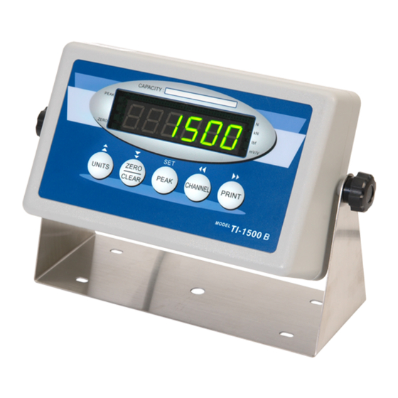
- Page 1 TI-1500B Force Gauge Digital Indicator Setup / Operation Manual V. A2...
-
Page 2: Table Of Contents
TABLE OF CONTENTS Page Chapter 1: Introduction To The TI-1500B Digital Indicator ............. 1 Chapter 2: Installation ........................2 2.1 Indicator Connect ......................... 2 Chapter 3: Configuration ........................3 3.1 Configuration Overview ......................3 3.2 Choosing Channel ........................3 3.3 Setup (“F”) Menu ........................3 3.4 User (“A”) Menu ......................... -
Page 3: Chapter 1: Introduction To The Ti-1500B Digital Indicator
All setup parameters may be entered via the front panel keys, including calibration. If your Model TI-1500B digital indicator is part of a complete force gauge or has been installed for you, you may skip to Chapter 7 for operating instructions. Prior to using the indicator, please read this chapter carefully and completely. -
Page 4: Chapter 2: Installation
Figure 2-2: Pin assignments for the Load Cell Port 2.1.2 Connecting the serial printer, remote display or computer The TI-1500B indicator comes standard with one full duplex RS-232 serial port, designed for connection to either a PC, a serial printer or a remote display. Figure 2-4... -
Page 5: Chapter 3: Configuration
Chapter 3: Configuration 3.1 Configuration Overview The TI-1500B indicator includes four absolute data channels. Before using the channel, please set the parameters for the channel which has been used. Finished parameter setting and system calibrating, in general force gauge mode, the system will be work convenience by changing the data channel. -
Page 6: User ("A") Menu
1. After choosing the data channel, the indicator shows “CH X”, use the SET(PEAK) key entering the Setup (“F”) Menu. X --- Channel No. 3.3.2 Navigating in the Setup Menu Use the directional keys shown in Figure 3-1 to move around in the Setup Menu. 1. -
Page 7: Chapter 4: Setup Menu
3. Move the switch to the right. 4. Power on the indicator. The indicator shows “CH X”, use PESK (SET) key entering the User (“A”) Menu, use the CHANNEL ( ) key or the PRINT ( ) key to move right or left in the Setup (“F”) menu until the indicator shows “A1”. -
Page 8: Setup Menu Descriptions
Setup Menu Descriptions This section provides more detailed descriptions of the selections found in the Setup Menu Chart. Factory-set defaults are shown in bold with a checkmark (√ ). Table 4-1 shows the selections that are not allowed for “Legal-for-Trade” applications. Name / Code Description Code / Value... -
Page 9: Chapter 5: User Menu
Name / Code Description Code / Value View zero and span calibration value. The values displayed Calibration in this function are valid only after Calibration ( F16 & F17 ) has been successfully completed. Allows you to key-in zero calibration value in case of Key-in Zero memory loss in the field. -
Page 10: Zero Calibration (F16)
In the unlikely event that either value is lost while in the field, the setup menu makes provisions for re-entering these values via F19 and F20, thus eliminating the need for re-calibration with test weights. Note: This chapter assumes that the indicator is in Setup (“F”) Menu mode. If the indicator is not in Setup Menu mode, refer to Chapter 3 for instructions. -
Page 11: View Calibration Values (F18)
Note: If you want to set one cal point, please press PEAK (SET) key twice, when the display shows “C 2”. 7. If the calibration was not successful, one of the error messages below will appear. Take the indicated action to correct the problem, then perform a new calibration. “ERR0”... -
Page 12: Key-In Zero Calibration Value (F19)
1. While in the Setup mode, scroll to “F19”, then scroll down once using the ZERO ( key. 2. The display will momentarily show “ET C0”, followed by a flashing zero. Use the four directional keys to adjust the displayed value to the zero calibration value. 3. -
Page 13: Chapter 7: Operation
N, kN, LBF, MV/V Indicates the unit of the displayed weight. 7.2 Keyboard TI-1500B is composed of five function keys. Refer to Figures 7-2 for the overall layout and key locations. Figure 7-2: TI-1500B Function Keys Layout... -
Page 14: General Scale Operation
0. When pressing the CHANNEL ( ) key, the system will automatic delay 2—5 seconds, then enter the next channel. TI-1500B has four absolute channels for custom using in the different load cell standard sources. Note: In general operate mode, just using CHANNEL key to change the channels. -
Page 15: Chapter 8: Legal For Trade Sealing
Chapter 8: Legal for Trade Sealing 8.1 Lead Sealing Indicators in the ABS enclosure can be sealed for commercial (Legal for Trade) application as follows: 1. Power off the indicator. 2. On the back of the indicator, locate the DIP switch cover. 3. -
Page 16: Appendix B: Serial Port Information
Additional Symbols Peak, Zero, N, kN, lbf, mV/V Keyboard 5 – key flat membrane panel Mechanical: Overall Dimensions (Standard) 310mm x 100mm x 205mm Appendix B: Serial Port Information B.1 Demand Mode The Demand mode allows control from a host device, usually a PC, and can be activated by pressing the PRINT key on the indicator’s front panel. -
Page 17: Recognized Host Commands
B.2 Recognized Host Commands “P” - This command is sent to the indicator to print the indicator display. The indicator will not respond if the system is in motion, positive overload or negative overload. “Z” – This command is sent to the indicator to zero the system. The indicator will not respond if the system is in motion, positive overload or negative overload. - Page 18 Global headquarters Sales: +1-800-503-9180 Office: +1-847-419-9180 Fax: +1-847-419-1515 E-mail: sales@transcell.com Add: 975 Deerfield Parkway Buffalo Grove, IL, 60089 U.S.A www.transcell.com Asia Pacific headquarters Tel:+886-2-8919-1012 Fax:+886-2-8919-1011 E-mail : info.apac@transcell.com Add: 7F, No. 129, Ln, 235, Baoqiao Rd., Xindian Dist., New Taipei, 231, Taiwan China headquarters 电话:+86-4008-803-808 传真:+86-25-5276-0038...
Need help?
Do you have a question about the TI-1500B and is the answer not in the manual?
Questions and answers