Advertisement
Owner's Manual & Safety Instructions
Save This Manual
operating, inspection, maintenance and cleaning procedures. Write the product's serial number in the
back of the manual near the assembly diagram (or month and year of purchase if product has no number).
Keep this manual and the receipt in a safe and dry place for future reference.
Email our technical support at: productsupport@harborfreight.com
When unpacking, make sure that the product is intact
and undamaged. If any parts are missing or broken,
please call 1-888-866-5797 as soon as possible.
©
Copyright
2017 by Harbor Freight Tools
No portion of this manual or any artwork contained herein may be reproduced in
any shape or form without the express written consent of Harbor Freight Tools.
Diagrams within this manual may not be drawn proportionally. Due to continuing
improvements, actual product may differ slightly from the product described herein.
Tools required for assembly and service may not be included.
Keep this manual for the safety warnings and precautions, assembly,
Visit our website at: http://www.harborfreight.com
®
. All rights reserved.
Read this material before using this product.
Failure to do so can result in serious injury.
SAVE THIS MANUAL.
17j
Advertisement

Subscribe to Our Youtube Channel
Related Manuals for Bauer 1695E-B


Summary of Contents for Bauer 1695E-B
- Page 1 Owner’s Manual & Safety Instructions Save This Manual Keep this manual for the safety warnings and precautions, assembly, operating, inspection, maintenance and cleaning procedures. Write the product’s serial number in the back of the manual near the assembly diagram (or month and year of purchase if product has no number). Keep this manual and the receipt in a safe and dry place for future reference.
-
Page 2: Table Of Contents
Table of contents Safety ............2 Maintenance ..........12 Specifications ..........8 Parts List and Diagram ......14 Setup ............8 Warranty ............ 16 Operation ........... 10 WARNING SyMBOLS AND DEFINITIONS This is the safety alert symbol. It is used to alert you to potential personal injury hazards. -
Page 3: Safety
Electrical Safety 1. power tool plugs must match the outlet. 4. Do not abuse the cord. Never use the cord Never modify the plug in any way. for carrying, pulling or unplugging the Do not use any adapter plugs with grounded power tool. - Page 4 5. Maintain power tools. check for misalignment 7. Use the power tool, accessories and tool bits or binding of moving parts, breakage of parts etc. in accordance with these instructions, and any other condition that may affect the taking into account the working conditions power tool’s operation.
- Page 5 3. Wear suitable gloves to reduce the 6. Grip tool as lightly as possible (while still keeping vibration effects on the user. safe control of it). Let the tool do the work. 4. Use tools with the lowest vibration 7. To reduce vibration, maintain the tool as when there is a choice.
- Page 6 Grounding TO pREVENT ELEcTRIc SHOcK AND DEATH FROM INcORREcT GROUNDING WIRE cONNEcTION: check with a qualified electrician if you are in doubt as to whether the outlet is properly grounded. Do not modify the power cord plug provided with the tool. Never remove the grounding prong from the plug.
- Page 7 Extension cords 1. Grounded tools require a three wire extension cord. 7. Make sure the extension cord is properly wired Double Insulated tools can use either and in good electrical condition. Always replace a two or three wire extension cord. a damaged extension cord or have it repaired by a qualified electrician before using it.
-
Page 8: Specifications
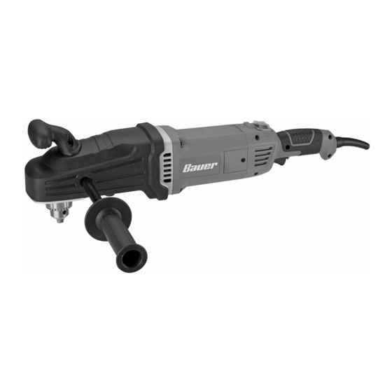
Specifications Electrical Rating 120VAC / 13A Chuck Capacity 5/64″ - 1/2″ Speed Setting High No Load Speed 450 RPM 1750 RPM Steel Capacity 1/2″ 5/16″ Wood Auger Bit Capacity 1-1/2″ 1-1/2″ Ship Auger Bit Capacity 1-1/2″ 1-1/2″ Self-feed Bit Capacity 4-5/8″... - Page 9 Functions Side Handle chuck Speed Switch Bottom Handle Rotation Button Direction Switch Trigger Bottom Handle chuck Key Other attached to Side power cord (not shown) Item 64121 For technical questions, please call 1-888-866-5797. Page 9...
- Page 10 Operating Instructions Read the ENTIRE IMpORTANT SAFETy INFORMATION section at the beginning of this manual including all text under subheadings therein before set up or use of this product. Tool Set Up TO pREVENT SERIOUS INJURy FROM AccIDENTAL OpERATION: Make sure that the Trigger is in the off-position and unplug the tool from its electrical outlet before performing any procedure in this section.
- Page 11 Workpiece and Work Area Set Up 1. Designate a work area that is clean and well lit. 3. Secure loose workpieces using a vise or clamps The work area must not allow access by children (not included) to prevent movement while working. or pets to prevent distraction and injury.
-
Page 12: Maintenance
Maintenance and Servicing procedures not specifically explained in this manual must be performed only by a qualified technician. TO pREVENT SERIOUS INJURy FROM AccIDENTAL OpERATION: Make sure that the Trigger is in the off-position and unplug the tool from its electrical outlet before performing any procedure in this section. - Page 13 Troubleshooting problem possible causes Likely Solutions Tool will not start. 1. Cord not connected. 1. Check that cord is plugged in. 2. No power at outlet. 2. Check power at outlet. If outlet is unpowered, turn off tool and check circuit breaker. If breaker is tripped, make sure circuit is right capacity for tool and circuit has no other loads.
-
Page 14: Parts List And Diagram
parts List and Diagram pLEASE READ THE FOLLOWING cAREFULLy THE MANUFACTURER AND/OR DISTRIBUTOR HAS PROVIDED THE PARTS LIST AND ASSEMBLY DIAGRAM IN THIS MANUAL AS A REFERENCE TOOL ONLY. NEITHER THE MANUFACTURER OR DISTRIBUTOR MAKES ANY REPRESENTATION OR WARRANTY OF ANY KIND TO THE BUYER THAT HE OR SHE IS QUALIFIED TO MAKE ANY REPAIRS TO THE PRODUCT, OR THAT HE OR SHE IS QUALIFIED TO REPLACE ANY PARTS OF THE PRODUCT. - Page 15 Assembly Diagram 77 78 Record product’s Serial Number Here: Note: If product has no serial number, record month and year of purchase instead. Note: Some parts are listed and shown for illustration purposes only, and are not available individually as replacement parts. Item 64121 For technical questions, please call 1-888-866-5797.
-
Page 16: Warranty
Limited 90 Day Warranty Harbor Freight Tools Co. makes every effort to assure that its products meet high quality and durability standards, and warrants to the original purchaser that this product is free from defects in materials and workmanship for the period of 90 days from the date of purchase.
Need help?
Do you have a question about the 1695E-B and is the answer not in the manual?
Questions and answers
Bauer M# 1695E-B PART # 15 How do I order part?