Table of Contents
Advertisement
Quick Links
SERVICE INSTRUCTIONS
for fuel-burning heater type
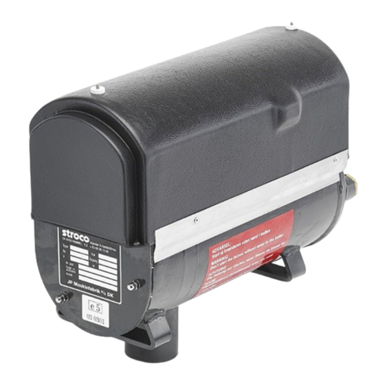
STROCO 15.00 M
Applicable from heater no.
12V: 238
24V: 405
STROCO ApS, Viborgvej 50, Voldby, DK-8450 Hammel, ph. +45 86961066, fax +45 86969647
Technical approval no. SP 555 AD 06
EU directive 42/245:
EU technical approval no. E5 10R-03152
Heating directive E 2001/56:
EU technical approval no. R122 E5 00002
ISO certified
Developed with aid from the Danish Environmental Protection Agency
GB 04/18
This manual is also available at www.stroco.dk
Advertisement
Table of Contents

Related Manuals for Stroco 15.00 M


Summary of Contents for Stroco 15.00 M
- Page 1 STROCO 15.00 M Applicable from heater no. 12V: 238 24V: 405 STROCO ApS, Viborgvej 50, Voldby, DK-8450 Hammel, ph. +45 86961066, fax +45 86969647 Technical approval no. SP 555 AD 06 EU directive 42/245: EU technical approval no. E5 10R-03152 Heating directive E 2001/56: EU technical approval no.
- Page 3 IMPORTANT The minimum conditions below must be met in order to maintain the right to claims under the warranty. 1. Installation must be carried out as described in this manual. 2. Service and maintenance must be performed in a proper professional manner.
- Page 4 IMPORTANT The heater must not be used in service stations. The heater must not be used where there is risk of ignition of flammable vapours and/or materials. Nor where there is risk of accumulation of toxic gasses, e.g. in closed spaces. The heater must not be used if the heater or its exhaust opening is near flammable materials, e.g.
-
Page 5: Table Of Contents
CONTENTS PAGE: Description ………………………………………………………………… 6-7 Schematic diagram of fuel-burning heater ………………………………... 7 Built-in dimensions …………………………………………………………. 8 Installation guide/installation plan ...…………………………………... 9-10 List of connections .………………………………………………………… 11 Electrical connections ..…………………………………………………... 12 Technical specifications ………………………………………………... 13-14 Explanation of terminology ..……………………………………………… 14 Maintenance …………………………………………………………….. 15-16 Description of functionality - operation ..…………………………………... -
Page 6: Description
DESCRIPTION It is important to read and understand this manual before using the STROCO heater to ensure optimum utility and safety. Please mail the warranty card to STROCO ApS. Fuel Water Heat Electrical power The presence of the above-mentioned basic elements, in the right quantities and correct mixtures, is essential to the heat production of the STROCO heater. -
Page 7: Schematic Diagram Of Fuel-Burning Heater
Precautionary measures are always better than repairs, and there are a number of Maintenance Procedures that should be undertaken regularly to ensure the continued working order of the heater. Please consult the maintenance section. Section 1 in the manual deals with the installation of the heater, i.e. -
Page 8: Built-In Dimensions
BUILT-IN DIMENSIONS All measurements +/- 2 mm. PAGE 8... -
Page 9: Installation Guide/Installation Plan
In case of replacement of hoses, use ONLY hoses from STROCO ApS, or hoses approved by STROCO ApS. The heater’s warranty will be void if any other hoses are used. Leaky hoses and joints lead to increased risk of fire. - Page 10 INSTALLATION GUIDE/INSTALLATION PLAN The vehicle must have safety measures to ensure that no exhaust ends up in rooms where there are people. The exhaust pipe should be max. 4000 mm in length and should be 65 mm in diameter. ...
-
Page 11: List Of Connections
LIST OF CONNECTIONS Water/fuel connection Pos 1: Exit for supply water: 3/4” thread Pos 2: Inlet for fuel supply (to the fuel pump of the heater from the fuel tank): Connection of fuel hose with 1/4 x 1/4 mm nipple. Pos 3: Exit for return fuel (to fuel tank): Fuel hose with 1/4 x 1/4 nipple. -
Page 12: Electrical Connections
ELECTRICAL CONNECTIONS The heater is available in two versions that can be used only for either 24V DC or 12V DC. The external connections are gathered in 8-pin connectors A and B. The internal connectors of the heater appears on a separate diagram, see page 32. Connect connectors as follows: Connector A: Connected to the circulation pump. -
Page 13: Technical Specifications
TECHNICAL SPECIFICATIONS Technical data: STROCO Fuel-burning heater type 15.00 M: Fuel-burning heater unit with integrated automatic controls and alarm functions. Dimensions L x W x H: 409 x 178 x 307 mm Weight: 17.5 kg Connections: The fuel-burning heater is connected to the electrical installation, fuel tank and water/heating system of the vehicle. -
Page 14: Explanation Of Terminology
TECHNICAL SPECIFICATIONS Pre-ventilation period: At first start approx. 60 sec. At restart approx. 10 sec. Post-ventilation period: approx. 120 sec. Under voltage: At 24V system: Connection or disconnection approx. 20.5/22 VDC At 12V system: Connection or disconnection approx. 10.5/11.5 VDC Over voltage: At 24V system: Connection or disconnection approx. -
Page 15: Maintenance
All fuel hoses should be replaced every 2 years. Use only hoses sourced from STROCO, or hoses approved by STROCO. The heater’s warranty will be void if it is fitted with hoses not approved by STROCO, or if there is no documentation of replacement of fuel hoses with 2 year intervals. - Page 16 Check fuel pressure; connect gauge to port ”P”. Adjust the pressure at port ”P1”; check with pressure gauge STROCO part no. 13.902. Unsteady gauge readings are a sign of air in the intake line. For fuel pressure, please consult the technical specifications.
-
Page 17: Description Of Functionality - Operation
DESCRIPTION OF FUNCTIONALITY - OPERATION The heater can be started using the main switch on the dashboard. Alternatively, a stating clock can function as main switch. The start-up process connects control current from the installation (12V or 24V battery). The main power supply is connected directly to the heater’s control system, which controls the power supply to the heater. -
Page 18: Description Of Functionality
DESCRIPTION OF FUNCTIONALITY Nozzle Operation thermostat Nozzle retainer Exit water 3/4“RG Nozzle retainer plate Outer boiler Photo Inner boiler Igniters Copper pins Flange Burner pipes Air shutter Entry water 3/4“RG Fan Wheel Chimney Fan motor Burner Automatic controls Foot Coupling Foot Fuel pump Oli pipes... -
Page 19: Troubleshooting - How
TROUBLESHOOTING - HOW? If you initiate troubleshooting because the heater is not working correctly, be sure to note the state and condition of the unit before and after the fault, if possible, in order identify the problem prior to repairs. Is the main switch or starting clock inactive? ... -
Page 20: Dismounting Burner And Combustion Chamber
DISMOUNTING BURNER AND COMBUSTION CHAMBER Access to the burner and combustion chamber is obtained by dismounting the end cover (pos. 31) at the three 6 mm nuts (pos. 29) and the three 6 mm stay bolts (pos. 32). Dismount the oil pipe (pos. 48) and the connectors (pos. 38). Remove the burner (pos. -
Page 21: Process Control Diagram
PROCESS CONTROL DIAGRAM PERIOD Pre-vent. Safety time Operating Post-ventilation TIME INTERVAL 60 (10) seconds 15 seconds heating time 120 seconds CONTROL PANEL Main Switch/clock Operating lamp Defect light AUTOMATIC BOX Low voltage relay Thermostat Photocell Safety thermostat Timer FUNCTION Circ.pump/relay Fan/oil pump motor Ignition Pre-heating... -
Page 22: Alarm Functionality
ALARM FUNCTIONALITY PAGE 22... -
Page 23: Combustion Unit
COMBUSTION UNIT The combustion unit is the heart of the combustion process. It mixes air with fuel vapour, which is ignited by a spark from the coil. The flame is registered by the photoelectric sensor. Correct setting of the combustion unit is important to ensure efficient combustion: Please observe the following: Electrode settings, as per page 24. -
Page 24: Voltage Control Of Electrodes
VOLTAGE CONTROL OF ELECTRODES Carried out when checking the ignition coil and ignition oscillator. During ignition control, the solenoid coil connector must be disconnected. Access to the burner unit is obtained by removing the end flange of the burner, unscrewing the three 6 mm nuts, and removing the burner. -
Page 25: Photoelectric Sensor
Troubleshoot the photoelectric sensor using STROCO testing device part no. 35.960. The sensor voltage should be 4.9V when the combustion unit is off. When the heater is operational, the voltage should be 0V. -
Page 26: Under/Overvoltage
The pump is running when the fan motor is running, but fuel is not released for atomisation in the nozzle until the solenoid valve is activated. It is important that the suction line of the pump is completely tight, and that a fuel filter (Stroco type 2000) has been mounted in the suction line. -
Page 27: Replacing The Fan Motor
The air setting affects the fuel combustion. Black smoke = not enough air, blue/grey smoke = too much air. Check the correct air setting using STROCO soot gauge part no. 13.982 or STROCO flue gas tester part no. 13.983 For combustion data, please see technical specifications. -
Page 28: Checking The Fuel Pump Solenoid Valve
CHECKING THE FUEL PUMP SOLENOID VALVE The simplest way to check the field coil is using a STROCO test device part no. 35.960. The field coil should draw 0.2A-0.4A power. An audible click from the solenoid valve indicates that the field coil is activated. -
Page 29: Operating Thermostat Sensor
Please note: This temperature range can be selected by not connecting cable B2 to chassis earth. The simplest way to check the temperature sensor is using STROCO testing device part no. 35.960. Activate the heater and raise the operating temperature to 22-85°C. The sensor is functional if the test device displays a temperature reading. -
Page 30: Assembly Drawing - Parts List
ASSEMBLY DRAWING - PARTS LIST Pos. Description Part number Nut for plastic cover 35.035 Plastic cover 15.034 Fuel hose 500 mm with 90° angle, biodiesel 35.178 Fuel hose 500 mm with 90° angle, biodiesel 35.178 Fan wheel 15.270 Fan motor 24/12V 15.340/15.342 Clip 15.017... -
Page 31: Assembly Drawing - Parts List
ASSEMBLY DRAWING - PARTS LIST PAGE 31... -
Page 32: Electrical Diagram
ELECTRICAL DIAGRAM PAGE 32... -
Page 33: Electrical Diagram
ELECTRICAL DIAGRAM PAGE 33... -
Page 34: Installation In Boats
INSTALLATION IN BOATS Fuel lines, fuel filter, melt-fuse valves, etc. Fuel lines must be made of either steel or copper, be permanently laid up and protected from me- chanical loads. Soft soldering is not allowed for any pipe joints. A fuse-melt valve must be inserted in the fuel line as close to the combustion chamber of the device as possible to disconnect the fuel flow if the outside temperature exceeds 80°C. - Page 35 INSTALLATION IN BOATS The sections below concern conditions to be given special consideration in connection with installa- tion in boats. General information In boats, the heater must be located as low as possible, and the exhaust must be outside. In all types of installation, the supplied circulation pump must be installed in the return line (cold).
- Page 36 INSTALLATION IN BOATS Rooms in which fuel-burner heater are installed must be equipped with ventilation in addition to the air required for combustion. All ventilation pipes from the heater must be led separately to a free deck, and the outlet must be kept free of superstructures, ect. The upper part of pipe must be able to take up heat expansion.
-
Page 37: Warranty Conditions
Warranty conditions for STROCO fuel-burning heaters A full service history with the heater’s number must be available to STROCO in order to settle warranty claims. The warranty may be void if the warranty card has not been properly filled in and returned to STROCO. -
Page 38: Dealers
DEALERS DANMARK, Denmar k: STROCO ApS Tlf. +45 86 96 10 66 Viborgvej 50, Voldby Fax +45 86 96 96 47 DK-8450 Hammel ENGLAND: GRAYSON THERMAL SYSTEMS Tlf. 0121 708 4000 257 Wharfdale Road Fax 0121 706 1886 Tyseley GB-Birmingham B11 2DP...
Need help?
Do you have a question about the 15.00 M and is the answer not in the manual?
Questions and answers