
Related Manuals for Axminster Craft AC305WL


Summary of Contents for Axminster Craft AC305WL
- Page 1 Code 105119 Original Instructions AC305WL Woodturning Lathes AT&M: 22/06/2018 BOOK REF : 105170...
-
Page 2: Eu Declaration Of Conformity
EN 61029-1:2009+A11 EN 61000-3-3:2008 Type Woodturning Lathe Model AC305WL conforms to the machinery example for which the EC Type-Examination Certificate No AM50361061, AE501701975 has been issued by Laizhou Chunlin Machinery Co., Ltd Signed at: No. 269 Baoshi Road, Wenfeng Street, Laizhou City, Shandong 261400 China and complies with the relevant essential health and safety requirements. -
Page 3: What's Included
What’s Included Quantity Item Part Model Number AC305WL Wood Lathe (Index Lock not fitted to the lathe) AC305WL Banjo arm (fitted) 150mm Tool rest (fitted to banjo arm) 75mm Faceplate (fitted to headstock) Axminster 4 Prong Drive Centre (25mm) (code 340106) Axminster Standard 60˚... -
Page 4: General Instructions For 230V Machines
General Instructions for 230V Machines The following will enable you to observe good • Leave machine unplugged until work is about to working practices, keep yourself and fellow workers commence. safe and maintain your tools and equipment in good • Always disconnect by pulling on the plug body and working order. -
Page 5: Specification
Specification Code 105119 Model AC305WL Rating Hobby Power 550W, 230V Speed (2) 500-2,040 and 1,000-4,080 Spindle Taper Spindle Thread 1” x 8tpi (Ref T04M) Taper Tailstock Distance Between Centres 457mm Max Diameter over Bed 305mm Tool Rest Stem Diameter 16mm... - Page 6 Assembly Fig 01-02 Fig 05 Fig 06 Tool Holder Locate the tool holder (I) the two Phillips screws and washers, see fig 3. Place a washer over the screws and screw them into the two pre-drilled holes below the headstock, see fig 4. NOTE: There are also two pre-drilled holes under the tailstock if you wish to mount the tool holder there.
- Page 7 Assembly Optional Bed Extension NOTE: DON’T TIGHTEN THE SCREWS AT THIS POINT! Locate the bed extension (K) and the two Hex screws and spring/washers, (see fig 7) position the bed Release the tailstock clamping lever and position the extension against the end of the lathe and line up tailstock across the join to align both beds, re clamp the pre-drilled holes, see figs 8-9.
-
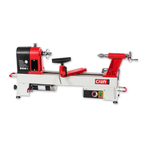
Page 8: Illustration And Parts Description
150mm Tool rest Tool rest lock Tailstock handle Motor handle lock Banjo arm lock Motor handle (ON) Push rod tool holder Motor (OFF) Lower pulley Variable speed control door lock Lathe bed Rubber foot AC305WL Control box Speed control dial... - Page 9 Illustration and Parts Description WARNING! MAKE SURE THE INDEX LOCK PIN IS IN THE UP POSITION BEFORE SWITCHING ON. Tailstock barrel lock Headstock Tailstock lock Power cable hooks Tool holder...
- Page 10 Illustration and Parts Description Fig 13 Fig 14 Index pointer Index locking pin Indexing assembly facility Tailstock barrel with scale Fig 15 Fig 16 Door knob spring lock Motor pulley access door Lower the headstock cover to reveal the pulley system Optional bed extension attached giving a maximum of 965mm between centres...
- Page 11 Operating Instructions Indexing Facility The indexing facility is useful for fluted columns, clock faces and accurate hole positioning. Lift and Rotate the index locking pin knob to unlock the headstock spindle, turn the faceplate and line up one of the positions then lower the indexing pin to lock the spindle in position, see figs 17-18-19-20. WARNING! DO NOT USE THE INDEX PIN WHEN REMOVING THE FACEPLATE OR CHUCK OTHERWISE THE PIN COULD BRAKE! Fig 17...
- Page 12 Operating Instructions Fig 23 Changing the Lathe Speed PLEASE NOTE THE FOLLOWING PICTURES SHOW THE AH-1218 LATHE. DISCONNECT THE LATHE FROM THE MAINS SUPPLY BEFORE CONTINUING! 1. Open the motor pulley access door by pulling the door knob back, see figs 21-22. Lower the headstock cover to access the pulleys, (see fig 23).
-
Page 13: Removing The Faceplate
4. Lower the motor to put tension back on the pulleys and lock in position. Raise the headstock cover and close the motor access door. Fig 26 Motor High AC305WL Pulley grooves NOTE: The speed chart above shows approximate speeds with the lathe off load. Removing the Faceplate... -
Page 14: Removing Drive/Live Centres
Removing Drive/Live Centres To remove the Drive Centre (F), locate the push rod (H), while holding the Drive Centre insert the push rod (H) through the centre hole of the headstock wheel and push the Drive Centre (F) out, see fig 27. Repeat the procedure for the Live Centre (G) in the tailstock, see fig 28. - Page 15 Exploded Diagrams/Lists...
- Page 16 Exploded Diagrams/Lists 1218VDA (AC305WL) Description Description Washer ø4 Bush Semi-circle head screwM4X8 Lock handle for tool rest base Hex socket screw M6×12 Headstock spur center Hand wheel Face plate Semi-circle head screwM6×24 Gear Semi-circle head screwM4X6 Round plate Hinge Headstock spindle...
- Page 17 Exploded Diagrams/Lists Switch-box Retaining ring 10 Strain relief Tailstock Strain relief Tailstock quill Cable Semi-circle head screw M5×12 Hex socket screw M10×25 Tailstock axis Washer ø10 Tool rack Cup center Lock nut Ball bearing Nut M10 Taper rod Rubber washer Support Nut M10 Semi-circle head screw M5×12...
-
Page 18: Wiring Diagram
Wiring Diagram... - Page 19 Notes...
- Page 20 The Axminster guarantee is available on Craft, Trade, Engineer, Air Tools & CNC Technology Series machines Buy with confidence from Axminster! So sure are we of the quality, we cover all parts and labour free of charge for three years! For more information visit axminster.co.uk/3years The packaging is suitable for recycling.
Need help?
Do you have a question about the AC305WL and is the answer not in the manual?
Questions and answers