
Summary of Contents for ROHRBACK COSASCO SYSTEMS CHECKMATE
- Page 1 CHECKMATE Reference Manual Cosasco 11841 Smith Avenue Santa Fe Springs, CA 90670 Tel: (562) 949-0123 P/N 723600-Manual Rev C www.cosasco.com Fax: +1 (562) 949-3065...
- Page 2 © 2005 Rohrback Cosasco Systems, Inc. All rights reserved. CHECKMATE™ is a trademark of Rohrback Cosasco Systems, Inc. CORROSOMETER and CORRDATA are registered trademarks of Rohrback ® ® Cosasco Systems, Inc. Windows is a registered trademark of Microsoft Corporation. ®...
- Page 3 TABLE OF CONTENTS Table of Contents Chapter 1 Introduction ................1 Chapter 2 Specifications ................3 Chapter 3 Installation ..................5 Chapter 4 System Configuration ..............9 Chapter 5 Reading Probes ................13 Chapter 6 Custom Probe Configuration ..........25 Chapter 7 Displaying Data ................29 Chapter 8 Transfering Data to the PC ............31 Chapter 9...
- Page 4 CHECKMATE™ Figures and Tables Figure Page CHECKMATE™ Instrument ..........2 CHECKMATE™ Battery Cover..........7 CHECKMATE™ Function Keys ..........9 Table Electrical Resistance Probe Types and Spans....23...
-
Page 5: Introduction
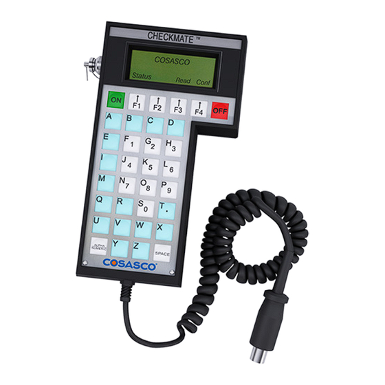
As with its predecessors, this portable unit has built-in memory that stores readings for later retrieval, however the CheckMate™ can store readings for up to 204 individual probes, with 10 readings per probe. Furthermore, the CheckMate™ makes transferring its stored data to a PC a much simpler process than before, using the included Corrdata CSV program. - Page 6 CHECKMATE™ 4.3” 2.0” 3.00” 7.75” 3.1” 20” MIN 80” MIN Figure 1.1 CheckMate™ Instrument...
-
Page 7: Specifications
SPECIFICATIONS CHAPTER 2 Specifications CheckMate™ Instrument Physical Dimensions: 7.75”H x 4.30”W x 2”D ( 196.8 mm x 109.2 mm x 50.8 mm ) Weight: 1.5 lb. ( 0.68 kg ) Temperature range: Operating F to 122 F ( -18... - Page 8 Automatic power shutoff in 2 minutes after reading or non-use Four Line Liquid Crystal Display (LCD) Supplied with: ER test probe 6 AA batteries CheckMate™ to computer cable (including DB25 to DB9 adapter) CD-ROM with Corrdata CSV PC software and manual ®...
-
Page 9: Installation
Carefully remove the instrument from its package. Included in the package you should find: CheckMate™ Instrumen Handheld CheckMate™ instrument ER test probe 6 AA batteries CheckMate™ to computer cable (including DB25 to DB9 adapter) USB with software and manual ... - Page 10 CHECKMATE™ Battery Installation The CheckMate™ is supplied with a set of six 1.5 Volt AA alkaline batteries. To install these batteries, remove the access panel on the back of the unit (see Figure 3.1) with the provided Allen Key and install the batteries with the...
- Page 11 Battery Cover Figure 3.1 Battery Cover of CheckMate™ Instrument A secondary, back up battery for stored readings in the CheckMate™ is provided by lithium batteries mounted internally within the unit. These batteries should provide 7-10 years of back up capacity. Replacement of these batteries requires the unit to be returned to Cosasco or an authorized dealer.
- Page 12 CHECKMATE™ To check that the unit is operational, press the ON button. The screen should appear as shown below: If the batteries are low or in need of replacement, a warning screen will appear as follows: If batteries are good, the instrument will sequence directly to the Standby display as below: The battery is tested both at initial switch on, and during probe measurement.
-
Page 13: System Configuration
System Configuration and Setup CheckMate™ Keypad The CheckMate™ features a 34-key keypad, with keys for the alphabet A through Z and numerals 0 through 9. The numerals are shared with letters F through P and S. Switch between these letters and the numbers using the “Alpha/Numeric” key. There are also four soft keys, F1 through F4 (as shown below). - Page 14 CHECKMATE™ Press Set Mate (F3) to go to the Mate Settings display: Press Set Time (F2) to go to the Mate Clock Set To display: Press Set (F2) to go to the Set Mate Date & Time display: From the keyboard, enter the last two digits of the year followed by the number of the month followed by the date followed by the time in hours followed by the time in minutes followed by 00.
- Page 15 SYSTEM CONFIGURATION AND SETUP Setting the Engineering Units To set the Engineering Units: From the Standby display, press SetUp (F4) to go to the Mate Configuration display: Press Set Mate (F3) to go to the Mate Settings display: Press Set Units (F1) to go to the Set Metal Loss Units display: Select and press Mils (F1) for mils (0.001”) and mils/year or press mm (F2) for millimeters and mm/year or um (F3) for micrometers and um/year.
- Page 16 CHECKMATE™ Clearing Memory on CheckMate™ Normally it will not be necessary to clear the memory on the CheckMate™ unless extraneous entries have been made, for example, when initially experimenting with the system. Alternatively, if the equipment is to be transferred to a new location, then it is recommended to clear the memory to avoid confusion with any previously collected data.
- Page 17 READING ER PROBES CHAPTER 5 Reading Electrical Resistance Probes Electrical Resistance probes can be read using three different procedures: Quick, ID and New. The Quick reading allows the user to read a probe and view the result in approximately 30 seconds.
-
Page 18: Table
A series of > symbols will accumulate from left to right across the display to indicate the progression of the measurement function At the conclusion of the measurement function (approximately 30 seconds) the CheckMate™ will display the probe reading and the check reading in divisions. A typical displayed reading is shown below: The Div: reading is the cumulative metal loss (corrosion) of the probe element on a scale of 1,000 divisions. -
Page 19: Table
READING ER PROBES The Chk: reading is a measure of probe functionality or integrity. The initial value for ER probes is 800 ±50 divisions. It is recommended that a CHECK reading be taken and recorded immediately after unpacking a probe as it will be the value to which all subsequent CHECK readings will be compared. -
Page 20: Table
CHECKMATE™ The instrument will automatically assign the next free ID number. If this is not acceptable you may press Clr (F2) and manually assign an ID from the keypad. Pressing BkSp (F3) backs up one space for each time it is pressed so that a change can be made. Pressing Exit (F4) returns to the Read Probe By display. - Page 21 READING ER PROBES The Enter Probe Tag display allows the user to enter up to twelve (12) alpha or numeric characters to uniquely identify the monitoring location. This can be a Tag No., location or process name. Pressing Clr (F2) clears a previously entered ID. Pressing BkSp (F3) backs up one space for each time it is pressed so that a change can be made.
- Page 22 Enter the ID number of the probe and press Enter (F1) The CheckMate™ will check the ID number to determine its validity. If the ID is valid, the Connect To Probe display will appear. If the ID is found to be invalid, the ID Not Found message will appear and the Exit key should be pressed to return to the Taking Probe Reading display.
- Page 23 A series of > symbols will accumulate from left to right across the screen to indicate the progression of the measurement function At the conclusion of the measurement function (approximately 30 seconds) the CheckMate™ will display the probe reading, the current check reading and the initial check reading in divisions. The initial check reading in divisions will be shown in parenthesis ().
- Page 24 CO. You may scroll up through the list by repeatedly pressing the Up (F2) key or down through the list by repeatedly pressing the Down (F3) key. When the probe element selection is displayed, press the Enter (F1) key to accept the selection. The CheckMate™ will automatically proceed to the next display based on the selection.
- Page 25 TF5 and TF50 ER provides the specific span for the probe. Alterna- tively, the nominal span can be used without appreciable error. Pressing Enter (F1) will cause the CheckMate™ to automatically go to the measure mode and the Taking Probe Reading – Please Wait display will appear:...
-
Page 26: Table
If OTHER is selected from the probe type selections on the Select Probe Type display the CheckMate™ will go to a second Select Probe Type display that allows the select the specific probe element conversion equation required and enter specific probe spans (in mils) that may be special. - Page 27 READING ER PROBES ER or TEMPERATURE Type Span Probe Element (mils) Strip Looop S4 Flush Element S4 Atmospheric Element S4 Strip Loop S8 Tube Loop T4 Flush Element S8 Atmospheric Element S8 Tube Loop T8 Flush Element S10 Cylindrical Element T10 Flush Element S20 Cylindrical Element T20 Wire Loop Element W40...
- Page 28 CHECKMATE™...
- Page 29 READING ER PROBES CHAPTER 6 Custom Probe Setup Probes may also be configured manually by following the procedure below: From the Standby display, press SetUp (F4) to go to the Mate Configuration display: Press Man Conf (F1) to go to the Enter Probe ID display: Enter a number between 51 and 255 and press Enter (F1) to go to the Enter Probe Tag display.
- Page 30 Down (F3) key. When the probe element selection is displayed, press the Enter (F1) key to accept the selection If a ER probe (element) is selected, the CheckMate™ will automatically proceed to the Enter Probe Alloy display:...
- Page 31 It does not affect the calculation of corrosion rates. If a TF5 or TF50 high sensitivity atmospheric ER probe has been selected, the CheckMate™ will go to a special Enter Probe Span display: Using the numeric portion of the keypad, enter the probe span in Angstroms (Ǻ).
- Page 32 CHECKMATE™ Pressing Enter (F1) will go to the ID Configured display:...
-
Page 33: Displaying Data
DISPLAYING DATA ON THE CHECKMATE™ CHAPTER 7 Displaying Data on the CheckMate™ Probe reading data can be displayed on the CheckMate™ either by the probe currently attached or by ID. The data includes the Tag ID, Metal Loss, Corrosion Rate, Divisions and Check Readings. - Page 34 CHECKMATE™ Press More (F1) one more time to go to the third screen of information:...
-
Page 35: Checkmate™ Instrument
Next, from the Select Menu, place a check next to the COM port to be used. Connect the CheckMate™ to the PC Connect the CheckMate™ instrument to the 9 pin COM port on the back of the PC using the provided cable. Make sure this is the same COM port as selected previously (in most cases this will be COM 1, however verify this in device manager). - Page 36 They may be opened using Excel or a similar spreadsheet program. If the CheckMate™ is not connected to the PC properly, or the PC is not running Corrdata CSV, the following screen may be displayed. Make sure that Corrdata CSV software is running, that the correct COM port is checked in the Select menu, and that the CheckMate™...
- Page 37 TROUBLESHOOTING GUIDE CHAPTER 9 Troubleshooting Guide Symptom Problem Solution CheckMate™ will not turn on. Batteries not installed. Install batteries (see Chapter 3) Battery voltage low. Install new batteries. Batteries installed incorrectly. Check the polarities as indicated on the unit. CheckMate™ turns off before 2 Battery voltage low.
- Page 38 CHECKMATE™...
Need help?
Do you have a question about the CHECKMATE and is the answer not in the manual?
Questions and answers