Table of Contents
Advertisement
Advertisement
Table of Contents

Related Manuals for Klemsan Klea 320P-D


Summary of Contents for Klemsan Klea 320P-D
- Page 1 Quadrant Energy Analyzer Quadrant Energy Analyzer User Manual...
-
Page 2: Table Of Contents
Quadrant Energy Analyzer TABLE OF CONTENTS SECTION 1 GENERAL INFORMATION ............8 Symbols ........................9 General Warnings ....................9 Receipt Control and Contents of Delivery ..........9 KLEA Energy Analyzer ..................10 KleaCom Software ....................11 KLEA Front Panel ....................12 Four-Quadrant Represantation ..............13 SECTION 2 INSTALLATION ...............14 Preparing for Installation .................15... - Page 3 Quadrant Energy Analyzer 3.2.1.1.3.5 Start of month ....................38 3.2.1.1.3.6 T1 kWh ........................38 3.2.1.1.3.7 T1 kWh E........................38 3.2.1.1.3.8 T1 kWh Imp. I.......................38 3.2.1.1.3.9 T1 kWh Imp. C.....................38 3.2.1.1.3.10 T1 kVArh Exp. I....................38 3.2.1.1.3.11 T1 kVArh Exp. C....................38 3.2.1.1.3.12 T2 kWh ........................39 3.2.1.1.3.13...
- Page 4 Quadrant Energy Analyzer 3.2.1.1.8.5 Q Menu ........................57 3.2.1.1.8.6 S Menu ........................57 3.2.1.1.8.7 CosØ Menu ......................57 3.2.1.1.8.8 PF Menu .........................58 3.2.1.1.8.9 IN Menu ........................58 3.2.1.1.8.10 F Menu ........................58 3.2.1.1.8.11 Temp. Menu ......................58 3.2.1.1.8.12 Harmonics V Menu .....................59 3.2.1.1.8.13 Harmonics I Menu ....................60 3.2.1.1.9 Clear Menu ......................60 3.2.1.2...
- Page 5 Quadrant Energy Analyzer 3.2.5.1.1.3 Phase3 Menu ......................81 3.2.5.1.1.4 Other ........................81 3.2.5.1.2 Daily Menu ......................81 3.2.5.1.3 Monthly Menu .....................81 3.2.5.2 Maximum Menu ....................81 3.2.5.3 Average Menu .....................81 SECTION 4 MODBUS PROTOCOL ............82 RS485 Wiring Diagram ..................83 Computer Connection ..................83 Message Format and Data Types of MODBUS-RTU Protocol .....83 Implemented functions for MODBUS-RTU Protocol ......84 Data and Setting Parameters for KLEA ...........84 4.5.1...
- Page 6 Quadrant Energy Analyzer Figure 3-11 Settings Menu ......................28 Figure 3-12 KLEA Save Query ....................29 Figure 3-13 Network Menu .....................29 Figure 3-14 Setting Current Transformer Ratio ..............30 Figure 3-15 Setting Voltage Transformer Ratio ...............30 Figure 3-16 Connection ......................31 Figure 3-17 Demand Period ....................31 Figure 3-18 Power Unit Setup ....................32 Figure 3-19...
- Page 7 Quadrant Energy Analyzer Figure 3-60 After Clear ......................61 Figure 3-61 Initial Value, After Clear Process ..............62 Figure 3-62 Date / Time Menu ....................62 Figure 3-63 System Info ......................63 Figure 3-64 Password ........................63 Figure 3-65 Restart........................64 Figure 3-66 Default Settings Command ................64 Figure 3-67 Measure Menu .....................65 Figure 3-68...
-
Page 8: General Information
Quadrant Energy Analyzer Quadrant Energy Analyzer SECTION 1 GENERAL INFORMATION... -
Page 9: Symbols
Quadrant Energy Analyzer SECTION 1 GENERAL INFORMATION BÖLÜM 1 GENERAL INFORMATION 1.1 Symbols Caution: Wherever used, this symbol indicates that there is important information that must be taken into consideration. Danger of Electric Shock: This symbol indicates that there is dangerous voltage or current. 1.2 General Warnings •... -
Page 10: Klea Energy Analyzer
Klea 320P-D base model 606131 Klea 320P-D optional digital IO model 606132 Klea 320P-D optional 2 analog outputs model 606133 Klea 320P-D optional 4 analog outputs model Please also check the contents of delivery as listed below: • 1 pc. KLEA •... -
Page 11: Kleacom Software
History (archive) data of Klea can be downloaded using KleaCom and this data can be listed in an MS Excel or WordPad file (selectable). KleaCom software is included in the CD-ROM received with Klea package. Latest version of KleaCom software can be downloaded from www.klemsan.com.tr. -
Page 12: Klea Front Panel
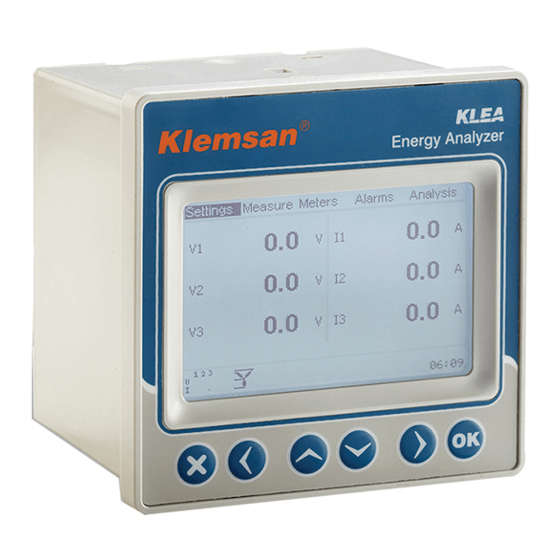
Quadrant SECTION 1 GENERAL INFORMATION Energy Analyzer 1.6 KLEA Front Panel Fig. 1-1 KLEA Display Menus L-N voltages belonging to three phases Currents of three phases Presence/Absence of currents-voltages belonging to three phases, and phase sequence Selected connection type Alarm state symbol (for any alarm) Temperature alarm state symbol (displayed only with a temperature alarm) Alarm relay symbol (If 1st and/or 2nd alarm relay is assigned to any alarm and also if there is an alarm in the system at the same time, this symbol shall appear on the... -
Page 13: Four-Quadrant Represantation
Quadrant Energy Analyzer SECTION 1 GENERAL INFORMATION 1.7 Four-Quadrant Represantation The angle(Ø) between voltage and current provides us information about the direction of energy fl w. A positive sign for active/reactive power indicates that active/reactive power is consumed. And also a negative sign for active/reactive power indicates that active/ reactive power is generated. -
Page 14: Installation
Quadrant Energy Analyzer Quadrant Energy Analyzer SECTION 2 INSTALLATION... -
Page 15: Preparing For Installation
Quadrant Energy Analyzer SECTION 2 INSTALLATION BÖLÜM 2 INSTALLATION This section provides the information about installation, mounting, cable routing and connections of Klea. 2.1 Preparing for Installation The purchased KLEA may not include all hardware options referred in this document. This situation does not constitute an impediment to the electrical installation. -
Page 16: Figure 2-1 Mounting Klea Into The Panel
Quadrant Energy Analyzer SECTION 2 INSTALLATION Fig. 2-2 Fixing KLEA to the panel There are 2.5mm2 and 1.5mm2 screwed female terminal blocks connected to fixed male terminal blocks on KLEA. Remove female terminal blocks and loosen their screws. Fig. 2-3 Loosening of Terminal Block Screws Before wiring up voltage and current ends to KLEA, you must be sure that the power is cut. -
Page 17: Figure 2-4 Inserting Cable Into The Terminal Block
Quadrant SECTION 2 INSTALLATION Energy Analyzer KLEA is connected to current transformer(s). Before disconnecting current transformer leads, be sure that they are short circuited elsewhere or connected to a parallel load which has sufficie tly low impedance. Otherwise dangerously high voltages will be induced at the current transformer leads. -
Page 18: Wiring Diagrams
Quadrant Energy Analyzer SECTION 2 INSTALLATION If KLEA is used together with current transformers, please pay attention to the following warning. Threshold values for proper operation of current transformers differ according to the type and size of the transformers being used. Before applying the points mentioned in the following warning, please check that the measured current value is larger than the current threshold value of the current transformer (Refer to manual or datasheet of the current transformer). -
Page 19: Three Phase Connection No Neutral (3P3W)
Quadrant Energy Analyzer SECTION 2 INSTALLATION 2.3.2 Three Phase Connection No Neutral (3P3W) Current Measurement Voltage Measurement Inputs Inputs Fig. 2-7 KLEA 3 Phase Delta Connection Diagram 2.3.3 Three Phase No Neutral Aron Connection Current Measurement Voltage Measurement Inputs Inputs Fig. -
Page 20: Digital Output Connection Diagram
Quadrant Energy Analyzer SECTION 2 INSTALLATION NOTE: Any two-phase current can be connected to the current measuring inputs. L1 and L3 are used in the figure above. 2.3.4 Digital Output Connection Diagram DO (+) DO (-) External DC Power Supply must be connected. load (5-30VDC) Fig. -
Page 21: Menus
Quadrant Energy Analyzer Quadrant Energy Analyzer SECTION 3 MENUS... -
Page 22: First Power-On" Settings
Quadrant Energy Analyzer SECTION 3 MENUS BÖLÜM 3 MENUS 3.1 “First Power-on” Settings After its receipt, when KLEA is switched on“for the first time”, the following page appears. Startup Settings Language English Date 07 January 2013 Time 17:45:28 Connection 3phase 4wire Start Fig. -
Page 23: Date
Quadrant Energy Analyzer SECTION 3 MENUS 3.1.2 Date In order to change the date, operator should press OK key, when“Date”tab is highlighted. Press right and left to move between day, month and year entries. Press up and down keys to change the values. Press OK key to complete date setting. Startup Settings Language English... -
Page 24: Time
Quadrant Energy Analyzer SECTION 3 MENUS 3.1.3 Time Time setting for KLEA is accomplished as explained in 3.1.2 Date menu. 3.1.4 Current Transformer Ratio (CTR) In this tab, current transformer ratio is entered. The current transformer ratio can be adjusted between 1-5000. When this tab is highlighted; if the operator presses OK key, KLEA Virtual Keyboard will appear on the screen. -
Page 25: Voltage Transformer Ratio (Vtr)
Quadrant Energy Analyzer SECTION 3 MENUS E.g.: ok clr ok clr ok clr ok clr Low limit Low limit Low limit Low limit High limit High limit High limit High limit 5000 5000 5000 5000 Startup Settings Language English Date 07 January 2013 Time 17:45:28... -
Page 26: Connection
Quadrant Energy Analyzer SECTION 3 MENUS Startup Settings Language English Date 07 January 2013 Time 17:45:28 Connection 3phase 4wire Start ok clr Low limit High limit 5000.0 Fig. 3-7 Voltage Transformer Ratio In order for KLEA to perform accurate measurements, current transformer ratio should be entered correctly. -
Page 27: Start
Quadrant Energy Analyzer SECTION 3 MENUS 3.1.7 Start When Start tab is selected, press OK key to initialize Klea. Startup Settings Language English Date 07 January 2013 Time 17:45:28 Connection 3phase 4wire Start Initializing ......Fig. 3-9 Start KLEA “first power-on” settings page only appears when KLEA is powered up for the first time after factory production. -
Page 28: Settings
Quadrant Energy Analyzer SECTION 3 MENUS At the top of the screen, there are multiple selection menus. In the middle, instantaneous voltage and current values pertaining to each phase are shown. At the bottom left of the screen, current and voltage values of the three phases and connection type are shown. -
Page 29: Network Menu
Quadrant Energy Analyzer SECTION 3 MENUS • Network • Device • Energy • Digital input • Digital output • Communication • Alarm • Clear The user can scroll inside the menus by pressing up and down keys. Press OK key in order to access contents of each submenus (the submenus under the setup menu) . -
Page 30: Current Transformer Ratio
Quadrant Energy Analyzer SECTION 3 MENUS 3.2.1.1.1.1 Current Transformer Ratio In this submenu current transformer ratio is entered. Inside Network menu, press up and down keys to select CTR. Press OK key and KLEA virtual keyboard will appear on the screen. -
Page 31: Connection
Quadrant Energy Analyzer SECTION 3 MENUS 3.2.1.1.1.3 Connection KLEA may perform measurements with three different connection types. • 3 phase – 4 wire connection • 3 phase – 3 wire connection • Aron connection Inside Network menu, press up and down keys to select Connection. Press OK key and the above connection types will appear on the screen. -
Page 32: Power Unit
Quadrant Energy Analyzer SECTION 3 MENUS 3.2.1.1.1.5 Power Unit KLEA displays total power or total energy values in two different units: • Mega • Kilo Inside Network menu, press up and down keys to select (highlight) ‘Power unit’ menu item. When ‘Power unit’ is selected, press OK key and the aforementioned options will appear on the screen. -
Page 33: Language
Quadrant Energy Analyzer SECTION 3 MENUS 3.2.1.1.2.1 Language Inside Device menu, press up and down keys to select (highlight) ‘Language’ menu item. When ‘Language’ is selected, press OK key and the options in Figure 3-20 will appear on the screen. Press up and down keys to select the desired option and press OK key to complete the setting. -
Page 34: Password Protection And New Password
Quadrant Energy Analyzer SECTION 3 MENUS 3.2.1.1.2.3 Password Protection and New Password KLEA has a password protection and default password protection is "Off". Default password is "1". New password can be adjusted between 1 - 9999 ( For Virtual Keyboard Refer to 3.1.4 E.g.). -
Page 35: Display On Time
Quadrant Energy Analyzer SECTION 3 MENUS 3.2.1.1.2.5 Display on Time Displayon time can be adjusted between 10 600 second. (For Virtual Keyboard Refer to 3.1.4 E.g.). 3.2.1.1.3 Energy Menu Initial energy values for T1, T1_1, T1_2, T1_3 and T2 can be entered inside this menu. Thus, Toperator can synchronize the official electric meter with KLEA tariff meters. -
Page 36: T1_2 Start Time
Quadrant Energy Analyzer SECTION 3 MENUS Meters->Imp. active Settings->Setup->Energy 1000.0 T1_1 start time T1 rate 1 1000.0 T1_2 start time T1 rate 2 1000.0 T1_3 start time T1 rate 3 1000.0 Start of day 1000.0 Start of month T1 kWh 1000.0 T1 kWh E. -
Page 37: T1_3 Start Time
Quadrant Energy Analyzer SECTION 3 MENUS NOTE: Assigned values also applies to the 4 quadrant counters. ("Exp. active "," Reactive R1 "," Reactive R2, " , " Reactive R3"," Reactive R4 ") 3.2.1.1.3.3 T1_3 StartTime ‘T1_3’ abbreviation refers to the third time slice of tariff 1 me er. T1_3 start time can be adjusted between 0-23 (for Virtual Keyboard Refer to 3.1.4 E.g.). -
Page 38: Start Of Day
Quadrant Energy Analyzer SECTION 3 MENUS 3.2.1.1.3.4 Start of day Start of day can be adjusted between 0 - 23. (for Virtual Keyboard Refer to 3.1.4 E.g.). 3.2.1.1.3.5 Start of month Start of month can be adjusted between 1 - 28. (for Virtual Keyboard Refer to 3.1.4 E.g.) The settings listed below (between... -
Page 39: T2 Kwh
Quadrant Energy Analyzer SECTION 3 MENUS 3.2.1.1.3.12 T2 kWh “Initial” value for meter of “ Imp. Active=>T2” can be entered in this tab. 3.2.1.1.3.13 T2 kWh E. “Initial” value meter of “ Exp. active=>T2” can be entered in this tab. 3.2.1.1.3.14 T2 kVArh Imp. -
Page 40: Digital Input Menu
Quadrant Energy Analyzer SECTION 3 MENUS 2054. modebus address:“Initial “energy value for meter of “Reactive R4 => T1 rate2” can be entered. 2056. modebus address:“Initial “energy value for meter of “Imp. active => T1 rate3” can be entered. 2058. modebus address:“Initial “energy value for meter of “Exp. active => T1 rate3 can be entered. 2060. -
Page 41: Input1 Menu
Quadrant Energy Analyzer SECTION 3 MENUS 3.2.1.1.4.1 Input1 Menu Input1 operates when DI1 and GND pins of KLEA are short circuited. Input1 menu has two settings: • Mode • Delay 3.2.1.1.4.1.1 Mode Mode options are as seen below (Fig. 3-30). Press up and down keys to scroll inside options. -
Page 42: Delay
Quadrant Energy Analyzer SECTION 3 MENUS 3.2.1.1.4.1.2 Delay Digital input delay can be adjusted between 10 2000 milliseconds. In order for ‘2nd tariff’ or ‘Counter’ modes to be activated; DI1 and GND pins should be short-circuited at least “delay” period of time. (for Virtual Keyboard Refer to 3.1.4 E.g.). -
Page 43: Input 3 Menu (Optional)
Quadrant Energy Analyzer SECTION 3 MENUS 3.2.1.1.4.3 Input 3 Menu (optional) Input 3 is applicable to optional digital IO Klea models. Input 3 applications and settings are the same as Input1. Digital input3 operates with DI3 and GND pins. 3.2.1.1.4.4 Input 4 Menu (optional) Input 4 is applicable to optional digital IO Klea models. -
Page 44: Output1 Menu
Quadrant Energy Analyzer SECTION 3 MENUS Measure Meters Settings Alarms Analysis Setup Network Output11 Date / Time Device Output2 System info Energy Output3 Password Digital input Output4 Restart Digital output Output5 Output6 Default settings Communication Alarm Output7 Clear 220.0 1 2 3 1 7 : 2 2 Fig. -
Page 45: Output1 Menu
Quadrant Energy Analyzer SECTION 3 MENUS Settings->Setup->Digital output->Output1 Mode Energy 1.000 T1 kWh Width T1 kWh E. Multiplier T1 kVArh I. Ind. T1 kVArh I. Cap. T1 kVArh E. Ind. T1 kVArh E. Cap. T2 kWh T2 kWh E. T2 kVArh I. Ind. T2 kVArh I. -
Page 46: Output2 Menu
Quadrant Energy Analyzer SECTION 3 MENUS Assume also that Digital input1 mode had been adjusted as“counter”. In this case, when Counter1 reaches 100 or multiples of 100, a pulse of 100 msec will be will be generated at the output pins DO1- and D01+. Assume that the digital input 1 counter value was 35 before multiplier adjustment. -
Page 47: Analog Output Menu (Optional)
Quadrant Energy Analyzer SECTION 3 MENUS 3.2.1.1.6 Analog Output Menu (Optional) Settings Measure Meters Alarms Analysis Setup Network Output11 Date / Time Device Output2 Output3 System info Energy Password Digital input Output4 Restart Digital output Default settings Analog output Communication Alarm 220.0 Clear... -
Page 48: Input Mode
Quadrant Energy Analyzer SECTION 3 MENUS Settings->Setup->Analog output->Output1 Input mode V1 (L-N) Output conn. 0-5V Min. value Max. value Multiplier Fig. 3-38 Output1 3.2.1.1.6.1.1 Input mode Analog output will generate a signal in accordance with the parameter selected in Input mode tab. -
Page 49: Output Connection
Quadrant Energy Analyzer SECTION 3 MENUS Settings->Setup->Analog output->Output1 Input mode V1 (L-N) V1 (L-N) Output conn. 0-5V V2 (L-N) Min. value V3 (L-N) Max. value Multiplier Fig. 3-39 Input mode 3.2.1.1.6.1.2 Output connection Inside Output1 menu, press up and down keys to select (highlight) ‘Output connection’ menu item. -
Page 50: Min. Value
Quadrant Energy Analyzer SECTION 3 MENUS Assume that for analog output 1, output connection was selected as 4-20 mA (refer to Fig. 3.40). Then, operator should adjust the “analog output 1” dip switch as seen in Fig. 3.42 (Vout1 -> OFF; Iout1 -> ON). After the dip switch adjustment, setting will be completed. Fig. -
Page 51: Multiplier
Quadrant Energy Analyzer SECTION 3 MENUS For example, assume that 10000000W and 350000000W are required to be entered for min. and max. values. In this case, if operator selected Mega in multiplier tab, then it will be sufficie t to enter 10 and 350 for min. and max. values. Settings->Setup->Analog output->Output1 Input mode V1 (L-N) - Page 52 Quadrant Energy Analyzer SECTION 3 MENUS The amplitude of analog output signal on AO1-GND pins will be as calculated by the following formula. AO1-GND =[ AO1 con.highlimit-AO1 con.lowlimit x (Meas. value-(Min value x Multip.))]+ AO1 con. low limit (Max value-Min value) x Multip. E.g.
-
Page 53: Output2 Menu
Quadrant Energy Analyzer SECTION 3 MENUS When measure is KLEA S tot.=1485000VAr, the result will be as follows, AO1-GND =[ 10-(-10) x(1485000-(1400x1000)] + (-10) = -5.75V (1800-1400)x1000 When measure is KLEA V1(L-N)=1695000VA , the result will be as follows, AO1-GND =[ 10-(-10) x(1695000-(1400x1000)] + (-10) = 4,75V (1800-1400)x1000 3.2.1.1.6.2 Output 2 Menu... -
Page 54: Baud Rate Menu
Quadrant Energy Analyzer SECTION 3 MENUS 3.2.1.1.7.1 Baud Rate Menu Inside Communication menu, press up and down keys to select (highlight) ‘Baud rate’ menu item. Press OK key and baud rate options will appear on the screen as seen in Figure 3-45. Scroll inside options by pressing up and down keys;... -
Page 55: L-N) Menu
Quadrant Energy Analyzer SECTION 3 MENUS 3.2.1.1.8.1 V(L-N) Menu Inside‘Alarm’ menu, when V(L-N) is highlighted, press OK key and the following page will appear on the screen. Settings->Setup->Alarm->V(L-N) Alarm relay Low limit High limit Delay Hysteresis Fig. 3-48 V(L-N) Menu Alarm relay : This setting is merely used to energize or not to energize a relay, when an alarm occurs. -
Page 56: Alarm Time Setting
Quadrant Energy Analyzer SECTION 3 MENUS Low Limit: Low limit value for the V(L-N) alarm. (For Virtual Keyboard Refer to 3.1.4 E.g.). In order to set an alarm for V(L-N), operator should enter a low limit value smaller than the high limit value. -
Page 57: L-L) Menu
Quadrant Energy Analyzer SECTION 3 MENUS Amplitude High limit Hysteresis % Waveform Hysteresis % Low limit Time Fig. 3-52 Alarm Example 3.2.1.1.8.2 V(L-L) Menu Alarm for phase-to-phase voltages is adjusted in this submenu. V(L-L) settings are the same as V(L-N). Low and high limit values can be adjusted between 0 2600000). 3.2.1.1.8.3 Current Menu Alarm for current is adjusted in this submenu. -
Page 58: Pf Menu
Quadrant Energy Analyzer SECTION 3 MENUS 3.2.1.1.8.8 PF Menu Alarm for power factor is adjusted in this submenu. Power factor settings are the same as V(L-N). Low and high limit values can be adjusted between: 0 1 . 3.2.1.1.8.9 IN Menu Alarm for neutral current is adjusted in this submenu. -
Page 59: Harmonics V Menu
Quadrant Energy Analyzer SECTION 3 MENUS Settings->Setup->Alarm->Current Alarm relay Relay1 Low limit Invalid limits! High limit Please check. Delay Hysteresis Fig. 3-54 Invalid Limits message 3.2.1.1.8.12 Harmonics V Menu Inside ‘Alarm’ menu, when Harmonics V is highlighted, press OK key and the following page will appear on the screen. -
Page 60: Harmonics I Menu
Quadrant Energy Analyzer SECTION 3 MENUS THDV hi limit Fig. 3-56 THDV High Limit Setting V3 --- V21 high limit: “3. ” , “ 5. ” …“21. ” harmonic distortion high limit values are entered. In order to set an alarm for V3, V5 –... -
Page 61: Before Clear
Quadrant Energy Analyzer SECTION 3 MENUS Scroll inside options by pressing up and down keys; press OK key to clear the desired option. When OK key is pressed,“Are you sure?” message will appear on the screen. Press again OK key to clear the parameter; press X key to exit with no change in the selected parameter. -
Page 62: Date / Time Menu
Quadrant Energy Analyzer SECTION 3 MENUS Assume that, initial value of “Setup->Energy->T1 kWh” was entered as 7500 kWh. In this case, after the clear process is completed, “Meters->Imp. active->T1 ” value will be 7500kWh. (Refer to Fig. 3.61). Meters->Imp. active 7500. -
Page 63: Password Menu
Quadrant Energy Analyzer SECTION 3 MENUS KLEMSAN Settings Measure Meters Alarms Analysis Setup Date / Time KLEA - Network Analyzer System info Model 606130 Password Serial number 2555953 Restart Default settings Language English Firmware version 1.00 220.0 PCB version 1.1.e0... -
Page 64: Default Settings
Quadrant Energy Analyzer SECTION 3 MENUS Settings Measure Meters Alarms Analysis Setup Date / Time Are you sure? System info Password Restart Default settings 220.0 1 2 3 1 7 : 2 2 Fig. 3-65 Restart 3.2.1.6 Default Settings This menu is used to return to factory default settings. All settings except date and time return to the factory defaults. -
Page 65: Instantaneous Menu
Quadrant Energy Analyzer SECTION 3 MENUS Measure Meters Alarms Analysis Instantaneous Demand Phasor diagram Signals 220.0 Harmonics 220.0 1 2 3 1 7 : 2 2 Fig. 3-67 Measure Menu 3.2.2.1 Instantaneous Menu This menu includes instantaneous values. If OK is pressed on this tab, the following page appears on the screen. -
Page 66: Demand Menu
Quadrant Energy Analyzer SECTION 3 MENUS If “3phase 3 wire” is selected as connection type, “VL-N” title in instantaneous menu will be replaced with “V”. In Measure-Instantaneous-P(active power) page; if active power value(of any phase) is positive (a “+” sign after the number), that phase consumes power, if active power value(of any phase) is negative (a “-”... -
Page 67: Current Month Menu
Quadrant Energy Analyzer SECTION 3 MENUS E.g.: The following graph shows the averages of current signals that are calculated/measured during the 15 minutes (demand period=15) and demand value. Amplitude Waveform 15 minutes 15 minutes 15 minutes Time (min) average value=3 amps average value=5 amps average value=4 amps demand=3A... -
Page 68: Current Menu
Quadrant Energy Analyzer SECTION 3 MENUS E.g.: Assume that start of day is “8”, and start of month is “26”; When time is 08.00 on 26th day of the month; “Current month” values will be assigned as “1 month ago” values, ... -
Page 69: Active Power Menu
Quadrant Energy Analyzer SECTION 3 MENUS This means: On October 10, 2012, demand value of phase1 current in the time interval 02:29:59 – 02:44:59, is 5.0 A. In order for KLEA to keep demand values for “1 month ago”, “2 months ago” and “3 months ago”;... -
Page 70: Months Ago Menu
Quadrant Energy Analyzer SECTION 3 MENUS 3.2.2.2.3 2 Months Ago Menu The demand values on the 2 months ago menu are as explained in the “Demand->Current Month” submenu. 3.2.2.2.4 3 Months Ago Menu The demand values on the 3 months ago menu are as explained in the “Demand- >Current Month”... -
Page 71: Harmonics Menu
Quadrant Energy Analyzer SECTION 3 MENUS Measure->Signals->V2-I2 Measure Meters Alarms Analysis Instantaneous 150.0V Demand 3.0A Phasor diagram 50.0Hz Signals 30.0° 150.0 Harmonics 150.0 V1-I1 V2-I2 V3-I3 1 2 3 1 7 : 2 2 Fig. 3-76 Signals Menu 3.2.2.5 Harmonics Menu KLEA measures/calculates current and voltage harmonics up to 51st harmonic. -
Page 72: Graph Menu
Quadrant Energy Analyzer SECTION 3 MENUS 3.2.2.5.2 Graph Menu Current and voltage harmonics of each phase are displayed graphically (Refer to Fig. 3-78). Operator can scroll inside graph menu by pressing right and left keys. There are 6 graph pages: V1, V2, V3, I1, I2, I3. Measure->Harmonics->V1 % 20 % 15 %... -
Page 73: T1 Tab
Quadrant Energy Analyzer SECTION 3 MENUS Meters Alarms Analysis Imp.active Exp. active Reactive R1 Reactive R2 Reactive R3 Reactive R4 Digital input Other 1 2 3 1 4 : 3 1 Fig. 3-80 Imp. Active Menu 3.2.3.1.1 T1 Tab. Import active energy values that belongs T1 are displayed as seen in the following figure: Meters->Imp. -
Page 74: T1 Rate2 Tab
Quadrant Energy Analyzer SECTION 3 MENUS Meters->Imp. active 302500.0 T1 rate1 99250.0 T1 rate2 98350.0 T1 rate3 104900.0 3506.0 Fig. 3-82 T1 rate1 import active energy 3.2.3.1.3 T1 Rate2 Tab. T1 Rate2 meter that belongs to T1, counts between T1_2 start time and T1_3 start time. Refer to: 3.2.1.1.3.2 3.2.1.1.3.3... -
Page 75: T2 Tab
Quadrant Energy Analyzer SECTION 3 MENUS Meters->Imp. active 302500.0 T1 rate1 99250.0 T1 rate2 98350.0 T1 rate3 104900.0 3506.0 Fig. 3-84 T1 rate3 import active energy 3.2.3.1.5 T2 Tab. Import active energy values that belongs T2 are displayed as seen in the following figure: Meters->Imp. -
Page 76: Digital Input Menu
Quadrant Energy Analyzer SECTION 3 MENUS 3.2.3.2 Digital Input Menu In this menu, counters belonging to digital inputs are displayed. Refer to 3.2.1.1.4 Digital input to adjust a digital input as a counter. When DI1 and GND pins are short-circuited for at least delay ( (Refer to 3.2.1.1.4.1.2 Delay) time, “digital input1 counter”... - Page 77 Quadrant Energy Analyzer SECTION 3 MENUS Alarm Time Stamp: Alarm time, 32 bit integer Alarm Definition: Alarm flag bit numbe . Refer to the example below Alarm State: Alarm ON or alarm OFF state. Alarm ON and alarm OFF conditions are both considered as records.
-
Page 78: Phase1 Menu
Quadrant Energy Analyzer SECTION 3 MENUS Alarms Analysis Phase 1 Phase 2 Phase 3 Other 220.0 220.0 1 2 3 1 7 : 2 2 Fig. 3-87 Alarms Menu 3.2.4.1 Phase1 Menu In Phase1 menu, phase1 alarm statuses are displayed. No alarm “Normal”... -
Page 79: Phase2 Menu
Quadrant Energy Analyzer SECTION 3 MENUS 3.2.4.2 Phase2 Menu “Phase2” menu consists of the same items as “Phase1” menu. Please refer to 3.2.4.1 Phase1 menu for details. 3.2.4.3 Phase3 Menu “Phase3” menu consists of the same items as “Phase1” menu. Please refer to 3.2.4.1 Phase1 menu for details. -
Page 80: Hourly Menu
Quadrant Energy Analyzer SECTION 3 MENUS Analysis Minimum 220.0 Maximum Average 220.0 220.0 1 2 3 1 7 : 2 2 Fig. 3-90 Analysis Menu Analysis menu parameters are not stored in permanent memory. As a result, all of analysis menu parameters will be cleared when Klea is turned-off. 3.2.5.1 Minimum Menu It consists of hourly, daily and monthly submenus. -
Page 81: Phase1 Menu
Quadrant Energy Analyzer SECTION 3 MENUS 3.2.5.1.1.1 Phase1 Menu Voltage(V), current(I), active power(P), reactive power(Q), apparent power(S), cos Ø, power factor(PF), and frequency(F) values are displayed. 3.2.5.1.1.2 Phase2 Menu Voltage(V), current(I), active power(P), reactive power(Q), apparent power(S), cos Ø, power factor(PF), and frequency(F) values are displayed. 3.2.5.1.1.3 Phase3 Menu Voltage(V), current(I), active power(P), reactive power(Q), apparent power(S), cos Ø, power factor(PF), and frequency(F) values are displayed. -
Page 82: Modbus Protocol
Quadrant Energy Analyzer Quadrant Energy Analyzer SECTION 4 MODBUS PROTOCOL... -
Page 83: Rs485 Wiring Diagram
Quadrant Energy Analyzer SECTION 4 MODBUS PROTOCOL BÖLÜM 4 MODBUS PROTOCOL 4.1 RS485 Wiring Diagram RS485 WIRING DIAGRAM Terminating Terminating device resistor resistor Fig. 4-1 RS485 Wiring Diagram 4.2 Computer Connection KLEA can communicate with PCs via USB-RS85 or RS232-RS485 converters. USB-RS485 or RS232-RS485 converter Fig. -
Page 84: Implemented Functions For Modbus-Rtu Protocol
Quadrant Energy Analyzer SECTION 4 MODBUS PROTOCOL There should be a time gap, which is at least 3.5 characters wide, between RTU messages. For instance, when client device requests any information, server device should reply after at least a 3.5 character wide time gap. Following the response of the server, client device should wait 3.5 characters long period, before requesting information again. -
Page 85: Read-Only Data
Quadrant Energy Analyzer SECTION 4 MODBUS PROTOCOL Operator/programmer can reach all measured and calculated data via ModeBUS RTU protocol. Starting address for measured and calculated data is 0. E.g.: Three phase average voltage is read via the 0th and 1th registers (16 bits + 16 bits = 32 bit). PC (or PLC) Request KLEA Response Slave ID... - Page 86 Quadrant Energy Analyzer SECTION 4 MODBUS PROTOCOL Address Parameter Description R/W Unit Data Type Phase 1 L1 V Phase1 voltage 32 bit flo t L1 I Phase1 current 32 bit flo t L1 P Phase1 active power 32 bit flo t L1 Q Phase1 reactive power 32 bit flo t...
- Page 87 Quadrant Energy Analyzer SECTION 4 MODBUS PROTOCOL Address Parameter Description R/W Unit Data Type L1 I Harmonics17 Phase1 current 17th harmonic 32 bit flo t L1 I Harmonics19 Phase1 current 19th harmonic 32 bit flo t L1 I Harmonics21 Phase1 current 21th harmonic 32 bit flo t L1 I Harmonics23 Phase1 current 23th harmonic...
- Page 88 Quadrant Energy Analyzer SECTION 4 MODBUS PROTOCOL Address Parameter Description R/W Unit Data Type L2 V Harmonics33 Phase2 voltage 33th harmonic 32 bit flo t L2 V Harmonics35 Phase2 voltage 35th harmonic 32 bit flo t L2 V Harmonics37 Phase2 voltage 37th harmonic 32 bit flo t L2 V Harmonics39 Phase2 voltage 39th harmonic...
- Page 89 Quadrant Energy Analyzer SECTION 4 MODBUS PROTOCOL Address Parameter Description R/W Unit Data Type L3 V Harmonics3 Phase3 voltage third harmonic 32 bit flo t L3 V Harmonics5 Phase3 voltage 5th harmonic 32 bit flo t L3 V Harmonics7 Phase3 voltage 7th harmonic 32 bit flo t L3 V Harmonics9 Phase3 voltage 9th harmonic...
- Page 90 Quadrant Energy Analyzer SECTION 4 MODBUS PROTOCOL Address Parameter Description R/W Unit Data Type L3 I Harmonics45 Phase3 current 45th harmonic 32 bit flo t L3 I Harmonics47 Phase3 current 47th harmonic 32 bit flo t L3 I Harmonics49 Phase3 current 49th harmonic 32 bit flo t L3 I Harmonics51 Phase3 current 51th harmonic...
- Page 91 Quadrant Energy Analyzer SECTION 4 MODBUS PROTOCOL Address Parameter Description R/W Unit Data Type Curr. Month L1 P Current Month Phase 1 Active Power 32 bit flo t Curr. Month L1 P time Current Month Phase 1 Active Power Timestamp 32 bit unix time Curr.
- Page 92 Quadrant Energy Analyzer SECTION 4 MODBUS PROTOCOL Address Parameter Description R/W Unit Data Type 1 month ago L2 S time 1 Month Ago Phase 2 Apparent Power Timestamp 32 bit flo t 1 month ago L3 P 1 Month Ago Phase 3 Active Power 32 bit unix time 1 month ago L3 P time 1 Month Ago Phase 3 Active Power Timestamp...
- Page 93 Quadrant Energy Analyzer SECTION 4 MODBUS PROTOCOL Address Parameter Description R/W Unit Data Type 3 months ago Total S time 3 Months Ago Total Apparent Power Timestamp 32 bit flo t 3 months ago L1 P 3 Months Ago Phase 1 Active Power 32 bit unix time 3 months ago L1 P time 3 Months Ago Phase 1 Active Power Timestamp...
- Page 94 Quadrant Energy Analyzer SECTION 4 MODBUS PROTOCOL Address Parameter Description R/W Unit Data Type 3 - Alarm Timestamp 3 - Alarm time 32 bit unix time 3 - Alarm ID 3 - Alarm ID 32 bit int. 3 - Alarm Status 3 - Alarm ON /Alarm OFF status 32 bit int.
- Page 95 Quadrant Energy Analyzer SECTION 4 MODBUS PROTOCOL Address Parameter Description R/W Unit Data Type 14 - Alarm Value 14 - Value of related alarm parameter 32 bit flo t 15 - Alarm Timestamp 15 - Alarm time 32 bit unix time 15 - Alarm ID 15 - Alarm ID 32 bit int.
- Page 96 Quadrant Energy Analyzer SECTION 4 MODBUS PROTOCOL Address Parameter Description R/W Unit Data Type 26 - Alarm Status 26 - Alarm ON /Alarm OFF status 32 bit int. 26 - Alarm Value 26 - Value of related alarm parameter 32 bit flo t 27 - Alarm Timestamp 27 - Alarm time 32 bit unix time...
- Page 97 Quadrant Energy Analyzer SECTION 4 MODBUS PROTOCOL Address Parameter Description R/W Unit Data Type 1034 37 - Alarm Value 37 - Value of related alarm parameter 32 bit flo t 1036 38 - Alarm Timestamp 38 - Alarm time 32 bit unix time 1038 38 - Alarm ID 38 - Alarm ID...
- Page 98 Quadrant Energy Analyzer SECTION 4 MODBUS PROTOCOL Address Parameter Description R/W Unit Data Type 1130 49 - Alarm Value 49 - Value of related alarm parameter 32 bit flo t 1132 50 - Alarm Timestamp 50 - Alarm time 32 bit unix time 1134 50 - Alarm ID 50 - Alarm ID...
- Page 99 Quadrant Energy Analyzer SECTION 4 MODBUS PROTOCOL Address Parameter Description R/W Unit Data Type 1274 Total Run minute counter Total Run minute counter dak. 32 bit int. 1276 Total On minute counter Total On minute counter dak. 32 bit int. Phase Energies(Double) 1278 Phase R Import Active Energy T1...
- Page 100 Quadrant Energy Analyzer SECTION 4 MODBUS PROTOCOL Address Parameter Description R/W Unit Data Type 1450 Phase T Reactive B1 => T1_3 Phase T Reactive Region-1 Tariff 1 ate2 Meter kVArh 64 bit double 1454 Phase T Reactive B1 => T2 Phase T Reactive Region-1 Tariff 2 eter kVArh 64 bit double 1458...
- Page 101 Quadrant Energy Analyzer SECTION 4 MODBUS PROTOCOL Address Parameter Description R/W Unit Data Type 1634 Phase T Reactive B4 => T2 Phase T Reactive Region-4 Tariff 2 eter kVArh 32 bit time_t (unix time) Digital Output Logs 1638 Log 1 Time stamp Log 1 Time stamp 32 bit time_t (unix time) 1640...
-
Page 102: Alarm Flags
Quadrant Energy Analyzer SECTION 4 MODBUS PROTOCOL Address Parameter Description R/W Unit Data Type 1724 Log 22 Data Log 22 Data 32 bit integer 1726 Log 23 Time stamp Log 23 Time stamp 32 bit time_t (unix time) 1728 Log 23 Data Log 23 Data 32 bit integer 1730... -
Page 103: Digital Input Flags
Quadrant Energy Analyzer SECTION 4 MODBUS PROTOCOL Alarms 1 THDV1 Sıc. VLL2 VLL1 V3 Harmonics V2 Harmonics V1 Harmonics THDV3 THDV2 VLL3 CosØ3 CosØ2 CosØ1 Alarms 2 I1 Harmonics THDI3 THDI2 THDI1 Battery Voltage I3 Harmonics I2 Harmonics 4.5.1.2 Digital Input Flags In order to understand related digital input active or passive, user should query 1446th modebus address. - Page 104 Quadrant Energy Analyzer SECTION 4 MODBUS PROTOCOL Abbreviations used for the Alarm Flags are: Temp. : Temperature : Phase1 (L-N) Voltage : Phase2 (L-N) Voltage : Phase3 (L-N) Voltage : Phase1 Current : Phase2 Current : Phase3 Current THDV1 : Phase1 Total Harmonic Distortion in Voltage THDV2 : Phase2 Total Harmonic Distortion in Voltage THDV3...
-
Page 105: Klea Setting Parameters
Quadrant Energy Analyzer SECTION 4 MODBUS PROTOCOL 4.5.2 KLEA Setting Parameters Operator/programmer should use‘10H - Write Multiple Registers and‘06H - Write Single Register’ to change settings parameters. Operator/programmer should use ‘0x3H - Read Holding Registers’ function to read setting parameters. 1 register ->... - Page 106 Quadrant Energy Analyzer SECTION 4 MODBUS PROTOCOL Address Parameter Data Type Descript. Unit Low Limit High Limit 2016 Start of day 32 bit int. hour 2018 Start of month 32 bit int. 2020 T1 kWh 32 bit flo t 20000000000.0 2022 T1 kWh E.
- Page 107 Quadrant Energy Analyzer SECTION 4 MODBUS PROTOCOL Address Parameter Data Type Descript. Unit Low Limit High Limit 2102 Input 2 Delay 32 bit int. 2000 Communication Settings 2104 Baud Rate 32 bit int. 2106 Slave ID 32 bit int. Alarms Gerilim (L-N) Alarmı...
- Page 108 Quadrant Energy Analyzer SECTION 4 MODBUS PROTOCOL Address Parameter Data Type Descript. Unit Low Limit High Limit 2174 Delay 32 bit int. 2176 Hysteresis 32 bit flo t Power Factor Alarm 2178 Alarm Relay 32 bit int. 2180 Low Limit 32 bit flo t 2182 High Limit...
- Page 109 Quadrant Energy Analyzer SECTION 4 MODBUS PROTOCOL Address Parameter Data Type Descript. Unit Low Limit High Limit 2252 I7 High Limit 32 bit flo t 2254 I9 High Limit 32 bit flo t 2256 I11 High Limit 32 bit flo t 2258 I13 High Limit 32 bit flo t...
- Page 110 Quadrant Energy Analyzer SECTION 4 MODBUS PROTOCOL Address Parameter Data Type Descript. Unit Low Limit High Limit 2358 Input5 Mode 32 bit int. 2360 Input5 Delay 32 bit flo t 2000 2362 Input6 Mode 32 bit int. 2364 Input6 Delay 32 bit int.
-
Page 111: Description List
Quadrant Energy Analyzer SECTION 4 MODBUS PROTOCOL Tablo 4-6 Description List 0-3phase 4wire 0-Mega 0-Off 0-Off 0-2400 0-Off 1-3phase 3wire 1-Kilo 1-T1 kWh 1-4800 1-Relay1 1-2nd tariff 2-Aron 2-T1 kWh E 2-9600 2-Relay2 2-Accumulator 3T1 -kVArh I. Ind. 3-Run hour 3-19200 4-T1 kVArh I. -
Page 112: Archive (History) Records
Quadrant Energy Analyzer SECTION 4 MODBUS PROTOCOL E.g.: If slave ID is assigned as 157; Request KLEA Response Slave ID Slave ID Function code Function code Starting address (high) Starting address (high) Starting address (Low ) Starting address (Low ) Number of registers (high) Number of registers (high) Number of registers (Low ) -
Page 113: Archive (History) Record Table
Quadrant Energy Analyzer SECTION 4 MODBUS PROTOCOL Tablo 4-7 Archive (History) Record Table Item No. History Records Variable Type Time Info (Timestamp) 32 bit int. L1 average voltage value (V ave.) 32 bit flo t L1 minimum voltage value (V1 min.) 32 bit flo t L1 maximum voltage value (V1 max.) 32 bit flo t... -
Page 114: Hourly Archive Data
Quadrant Energy Analyzer SECTION 4 MODBUS PROTOCOL Item No. History Records Variable Type L3 minimum reactive power value (Q3 min.) 32 bit flo t L3 maximum reactive power value (Q3 max..) 32 bit flo t L3 average apparent power value (S3 ave.) 32 bit flo t L3 minimum apparent power value (S3 min.) 32 bit flo t... - Page 115 Quadrant Energy Analyzer SECTION 4 MODBUS PROTOCOL If there is no enough memory for one more hourly data, the oldest record is deleted and the latest record is saved to first file memory. In this case, the last saved file number will be“1”. User can access this number with querying 1360th modbus address (refer to Table 4-4).
-
Page 116: Daily Archive Data
Quadrant Energy Analyzer SECTION 4 MODBUS PROTOCOL Request KLEA Response Slave ID 0x01 Slave ID 0x01 Function code 0x14 Function code 0x14 Byte Counts 0x07 Byte count 0x16 Sub-req. 1 reference type 0x06 Sub-req. 1 byte count 0x15 Sub-req. 1 file number HI 0x00 Sub-req. -
Page 117: Monthly Archive Data
Quadrant Energy Analyzer SECTION 4 MODBUS PROTOCOL For more information about record structure of Klea, please look at 4.5.3.1 Hourly archive data. The ‘last saved file number’ inside the daily memory can be accessed from the 32- bit parameter starting from Modbus address 1362 (Table 4-4). -
Page 118: Clear Address Table
Quadrant Energy Analyzer SECTION 4 MODBUS PROTOCOL Tablo 4-8 Clear Address Table Address Data Type Parameters/Records to be Cleared Value Modbus func. 1902 32 bit int. Energy meters 10H-06H 1904 32 bit int. Demand values 10H-06H 1906 32 bit int. Digital İnput Counters 10H-06H 1908... -
Page 119: Factory Default Settings
Quadrant Energy Analyzer Quadrant Energy Analyzer SECTION 5 FACTORY DEFAULT SETTINGS... - Page 120 Quadrant Energy Analyzer SECTION 5 FACTORY DEFAULT SETTINGS BÖLÜM 5 FACTORY DEFAULT SETTINGS Parameter Default value Unit Setting Range Network Settings Current Transf. Ratio (CTR) 1<=>5000 Voltage Transf. Ratio (VTR) 1<=>5000 Connection 3 phase 4 wire 3phase 4wire/3 phase 3wire/Aron Demand Period min.
- Page 121 Quadrant Energy Analyzer SECTION 5 FACTORY DEFAULT SETTINGS Parameter Default value Unit Setting Range T1_3 kVArh Imp. C. kVArh 0.0<=>20000000000.0 T2 kWh 0.0<=>20000000000.0 T2 kWh E. 0.0<=>20000000000.0 T2 kVArh Imp. I kVArh 0.0<=>20000000000.0 T2 kVArh Imp. C. kVArh 0.0<=>20000000000.0 T2 kVArh Exp. I kVArh 0.0<=>20000000000.0 T2 kVArh Imp.
- Page 122 Quadrant Energy Analyzer SECTION 5 FACTORY DEFAULT SETTINGS CosØ Low limit 0.000<=>1.000 High limit 0.000<=>1.000 0.000<=>1.000 Low limit High limit 0.000<=>1.000 Low limit 0.0<=>90000.0 High limit 0.0<=>90000.0 Low limit 35.0<=>70.0 High limit 35.0<=>70.0 Harmonics V Low limit 0.0<=>100.0 High limit 0.0<=>100.0 Harmonics I Low limit...
-
Page 123: Technical Specifications
Quadrant Energy Analyzer Quadrant Energy Analyzer SECTION 6 TECHNICAL SPECIFICATIONS... - Page 124 Quadrant Energy Analyzer SECTION 6 TECHNICAL SPECIFICATIONS BÖLÜM 6 TECHNICAL SPECIFICATIONS Supply Voltage 85..300V AC/DC Frequency 45..65 Hz Measurement Inputs Voltage 1..300 V RMS (L-N) Current 0.05..6 A RMS Frequency 45..65 Hz Measurement Accuracy Function Function Function Measuring Range Other Complementary Symbol Performance Characteristics...
- Page 125 Quadrant Energy Analyzer SECTION 6 TECHNICAL SPECIFICATIONS Analog Output 2 pcs. (2 pcs. analog output optional model) / 4 pcs. (4 pcs. analog output optional model) 0-5V, 0-10V, -5-5V, -10-10V, 0-20mA, 4-20mA Current Transformer Ratio (CTR) 1..5000 adjustable. Voltage Transformer Ratio (VTR) 1..5000 adjustable.
- Page 126 Quadrant Energy Analyzer Kızılüzüm Mahallesi Kemalpaşa Kızılüzüm Cad. No:15 - 35730 Kemalpaşa - İzmir / TURKEY Tel: (+90 232) 877 08 00 Fax: (+90 232) 877 08 06 www.klemsan.com / Revision No: 20032018 info@klemsan.com.tr...
Need help?
Do you have a question about the Klea 320P-D and is the answer not in the manual?
Questions and answers