Table of Contents
Advertisement
Quick Links
Advertisement
Table of Contents

Related Manuals for Klemsan POWYS 1110


Summary of Contents for Klemsan POWYS 1110
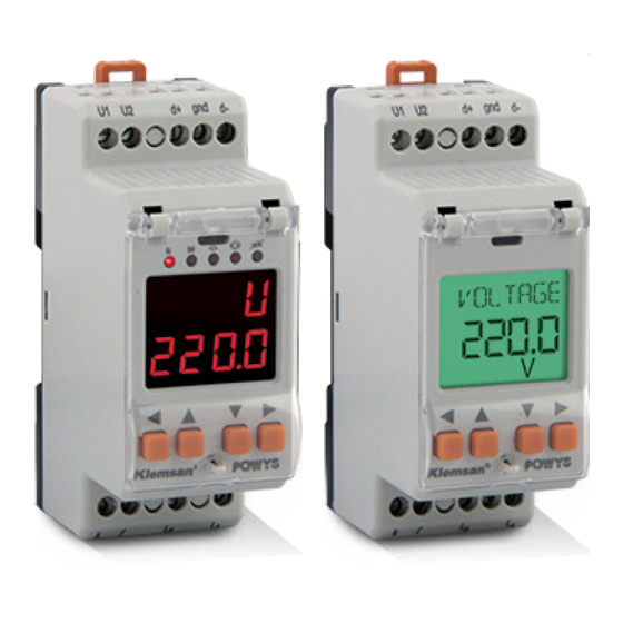
- Page 1 Energy Analyzer USER MANUAL...
-
Page 2: Table Of Contents
TABLE OF CONTENTS SECTION 1 GENERAL INFORMATION ............5 General Features ....................5 Poper Use and Safety Conditions ..............6 Connection Types ....................7 General View&Definitions.................. 7 Icons&Leds ......................8 Buttons&Their Functions ................... 8 Menu Structure ..................... 9 Four Quadrant Representation ..............13 SECTION 2 INSTALLATION ...............14 Preparation for Installation ................15... - Page 3 FIGURES Fig. 1-1 Connections ......................7 Fig. 1-2 General view of the device ................7 Fig. 1-3 LCD icon descriptions ..................8 Fig. 1-4 Segment display LED descriptions ..............8 Fig. 1-5 Four Quadrant Representation ..............13 Fig. 2-1 Connection Diagram ..................16 Fig.
-
Page 4: General Information
Enerji Analizörü SECTION 1 GENERAL INFORMATION... -
Page 5: General Features
SECTION 1 GENERAL INFORMATION SECTION 1 GENERAL INFORMATION 1.1 General Features POWYS 1xxx series is an energy analyzer designed for single phase systems, measuring the following parametres: • Voltage • Current • Network frequency • CosØ value • Power factor •... -
Page 6: Poper Use And Safety Conditions
SECTION 1 GENERAL INFORMATION • Adjustable LCD backlight on duration • Sealable cover • Low power consumption • A wide range of feeding and operating temperature Device model POWYS 1110 POWYS 1012 POWYS 1120 POWYS 1022 POWYS 1023 Order number... -
Page 7: Connection Types
The manufacturing company may not be kept responsible for unfavorable incidents that arise out of the failure to follow the above cautions. 1.3 Connection Types POWYS 1110 POWYS 1120 POWYS 1012 POWYS 1022 POWYS 1023 Fig. -
Page 8: Icons&Leds
SECTION 1 GENERAL INFORMATION 1.5 Icons&Leds The descriptions of the icons appearing on the display of the devices with LCD are provided as follows: activated when the import meters are shown activated when the reactive meters are shown activated when the active meters are shown activated when the reactive meters are shown activated when the total run hour is shown activated when the total on hour is shown... -
Page 9: Menu Structure
SECTION 1 GENERAL INFORMATION In the ENERGY, COUNTER, ASSIGNING PRE In the MEASUREMENTS HARMONICS, SETTINGS VALUES TO THE CHANGE SETTINGS menus menus METERS SHORT LONG SHORT SHORT LONG SHORT LONG LONG PRESSING PRESSING PRESSING PRESSING PRESSING PRESSING PRESSING PRESSING ( t > 2sec ) ( t <... -
Page 10: Instantaneous Measurements And Submenus (Lcd Devices)
SECTION 1 GENERAL INFORMATION menu demand ↕ ↕ ↕ ↔ VOLTAGE ↔ ↔ ↔ ↔ ↕ ↕ ↕ ↕ ↔ CURRENT ↔ ↔ ↔ demand ↔ ↕ ↕ ↕ ↕ ↔ FREQ ↔ ↔ ↔ ↕ ↕ ↕ ↔ COSQ ↔... -
Page 11: Table 1-3 Instantaneous Measurements And Submenus (7-Segment Devices)
SECTION 1 GENERAL INFORMATION menu demand ↕ ↕ ↕ ↔ Uolt ↔ H - U ↔ L - U ↔ ↔ ↕ ↕ ↕ ↕ ↔ Curr ↔ H - I ↔ L - I ↔ d - I ↔ ↕... -
Page 12: Table 1-4 Energy, Counter, Harmonics And Settings Menus
SECTION 1 GENERAL INFORMATION ↔ IMPORT ACTIVE ↕ ← EXPORT ACTIVE ENERGY ↕ ← IMPORT REACTIVE ↕ ← EXPORT REACTIVE ↕ ↔ RUN HOUR ↕ ← ON HOUR COUNTERS ↕ ← POWER INT. COUNTER ↕ ↔ V HARM 1 ↕ ←... -
Page 13: Four Quadrant Representation
SECTION 1 GENERAL INFORMATION 1.8 Four Quadrant Representation The angle(Ø) between voltage and current provides us information about the direction of energy flow. A positive sign for active/reactive power indicates that active/reactive power is consumed. And also a negative sign for active/reactive power indicates that active/reactive power is generated. Fig. -
Page 14: Installation
Energy Analyzer SECTION 2 INSTALLATION... -
Page 15: Preparation For Installation
SECTION 2 INSTALLATION SECTION 2 INSTALLATION 2.1 Preparing for Installation The purchased product may not include all hardware options referred in this document. This situation does not constitute an impediment to the electrical installation. Assembly and related connections of the product, must be implemented by authorized persons in accordance with the instructions of user manual. -
Page 16: Digital Output Connection Diagram
SECTION 2 INSTALLATION Current Voltage Fig. 2-1 Connection Diagram 2.3.2 Digital Output Connection Diagram DO (+) DO (-) External DC Power Supply must be yük connected. (5-30VDC) Fig. 2-2 Digital Output Connection Diagram ( POWYS 10xx ) -
Page 17: Dimensions (Mm)
SECTION 2 INSTALLATION 2.4 Dimensions (mm) Fig. 2-3 Dimensions... -
Page 18: Menus
Energy Analyzer SECTION 3 MENUS... -
Page 19: Instantaneous Measurements
SECTION 3 MENUS SECTION 3 MENUS 3.1 Instantaneous Measurements Instantaneous measurement menus and the menus showing their related maximum, minimum and demand values are provided in the following table. As provided in the table, down, up, right and left handside buttons provide menu switches. Example of React ve Example of React ve power d splay for LCD... -
Page 20: Energy Meters (Energy Menu)
SECTION 3 MENUS Example of React ve Example of React ve power d splay for LCD power d splay for dev ces 7-segment dev ces Fig. 3-2 Example of demand page (Active power) “- - - -” icon appearing in the menus which shows minimum values refer to the fact that no value has yet to be saved as a minimum value. -
Page 21: Prevalue Assignme
SECTION 3 MENUS LCD display devices 7-segment display devices "imp" and "act" icons flash on the screen Menu title: I.Act. ↔ IMPORT ACTIVE ↕ "exp" and "act" icons flash on the screen Menu title: E.Act. ← EXPORT ACTIVE ENERGY ↕ "imp"... -
Page 22: Counters Menu
SECTION 3 MENUS If the changes are to be saved: Press the right button so that “NO” sign starts blinking. Pressing the down/up buttons, “NO” sign turns into “YES” sign. Then, pressing the left button, save the changes. If the changes are to be cancelled: Press the right button so that “NO”... -
Page 23: Settings Menu
SECTION 3 MENUS LCD display devices 7-segment display devices "run" icon flashes on the screen Menu title : run ↔ RUN HOUR ↕ "on" icons flashes on the screen Menu title: on ← ON HOUR COUNTERS ↕ POWER INT. "int" icons flashes on the screen Menu title: Int ←... - Page 24 SECTION 3 MENUS Submenu Description Menu Submenu 1 Submenu 2 Submenu 4 Settings Basic settings BASIC Current transformer ratio (bSc) Voltage transformer ratio Alarm settings Voltage alarm settings V ALM Voltage alarm upper limit (Uolt) SETTING S hYSt Voltage alarm lower limit ALARMS dlY.t Voltage alarm hysteresis value...
- Page 25 SECTION 3 MENUS Voltage alarm settings Voltage alarm upper limit V ALM Voltage alarm lower limit (Uolt) hYSt Voltage alarm hysteresis value dlY.t Voltage alarm delay time Current alarm settings Current alarm upper limit I ALM Current alarm lower limit (Curr) hYSt Current alarm hysteresis value...
- Page 26 SECTION 3 MENUS Digital output options (ATTENTION! : This menu is only valid for devices with digital output) 1st digital output settings 1st digital output type settings OUT1 tYPE PULSE (PuLS) Assign as pulse output (Out1) LOW ALM (ALr.L) Assign as low alarm output DIG OUT HIGH ALM (ALr.H) Assign as high alarm output...
- Page 27 SECTION 3 MENUS Password protection timeout duration. After entering the password, if no other button Pin.t is pressed or no setting is changed with MODBUS, password protection is activated at the end of the period. Password value Display setting Menu settings Menu browsing setting ScrL Menu browsing off...
-
Page 28: Value Changing
SECTION 3 MENUS Informing INFO (InFo) Firmware version information Table 3-1 SETTINGS Menu tree 3.8 Value Changing There are 2 different value changing menus: • Multiple choice menus: Theese menus enable predefined options. In these menus, press the right button so that the first option of the menu starts to blink. Press the up/down buttons so that the option starts blinking in the screen. -
Page 29: Demand Time Setting (Demand)
SECTION 3 MENUS If you go outside of the alarm limit values: • The value in the indicator for the related parameter starts blinking. • Alarm icon or alarm LED is enabled on the display at the end of the delay time. •... -
Page 30: Digital Output Settings (Dig Out)
SECTION 3 MENUS Baudrate (bAud): Refers to the signal rate used in communication in terms of “baud”. Communication rate may be modified within the range of setting. Slave ID (Id): RS485 communication works based on the communication of one master and one or more than one slave devices. -
Page 31: Password Settings (Security)
SECTION 3 MENUS Output parameter setting (OUT): This menu enables to set from which parameter output is to be given. If the “OFF” option is selected, it also turns off the related output. Pulse duration setting (durA): This menu enables to set for how long the pulse is going to remain active. Pals step range (rAt): This menu enables to set for how long the pulse is going to remain active. -
Page 32: Clear Menu (Clear)
SECTION 3 MENUS • Menu screening duration (Scr.P): While the menu browsing mode is on, this menu enables to determine the screening duration of each menu in seconds. When the browsing mode is off, it has no effect. • Homepage setting (Strt): When the device is powered, it is the first menu opening page that will come to the display. -
Page 33: Confirmation Procedure
SECTION 3 MENUS 3.18 Confirmation Procedure The following query appears on the display to confirm or cancel the activity to apply: To confirm the activity: Press the right button so that “NO” sign starts blinking. Pressing the up/down buttons,“NO” icon turns into “YES”. -
Page 34: Rs485 Communication
Energy Analyzer SECTION 4 RS485 COMMUNICATION... - Page 35 SECTION 4 RS485 COMMUNICATION SECTION 4 RS485 Communication RS485 communication is built by using the “MODBUS RTU” protocol. The functions that are supported are as follows: • 03H function: Readable addresses can be read with using this function in the modbus table.
- Page 36 SECTION 4 RS485 COMMUNICATION 40055 Current Harmonic - 3 float 40057 Current Harmonic - 5 float 40059 Current Harmonic - 7 float 40061 Current Harmonic - 9 float 40063 Current Harmonic - 11 float 40065 Current Harmonic - 13 float 40067 Current Harmonic - 15 float...
- Page 37 SECTION 4 RS485 COMMUNICATION 40135 Run Hour Meter 32 bit integer R / W If the password protection is enabled, enter your password in the “Setting Protection” address and then enter the value “2222” in the “Activating Meter Change” address. Later on, you may enter a value.
- Page 38 SECTION 4 RS485 COMMUNICATION 40149 Current transformer ratio 32 bit integer R / W (CTR) 40151 Voltage transformer ratio float R / W (VTR) 40153 Demand Duration 32 bit integer R / W 40155 Password activation 32 bit integer R / W 40157 Password activation 32 bit integer...
- Page 39 SECTION 4 RS485 COMMUNICATION 40209 Cosφ Alarm Upper Limit float R / W 40211 Cosφ Alarm Lower Limit float R / W 40213 Cosφ Alarm Hysteresis float R / W 40215 Cosφ Alarlm Delay Time 32 bit integer R / W 40217 Power Factor Alarm Upper float...
-
Page 40: Applying Multiple Option Settings With Modbus
SECTION 4 RS485 COMMUNICATION 42001 Save the changes 32 bit integer If the password protection is enabled, you should enter a password in the “Settings Protection” addres. Write “1” to save the changes and restart 45001 Activate the Meter Change 32 bit integer If the password protection is... -
Page 41: Status Flags
SECTION 4 RS485 COMMUNICATION 40187 Homepage setting VOLTAGE CURRENT FREQ COSQ POWER P POWER Q POWER S THD V THD I 40189 Display Backlight DURATION DEP Options CONT ON CONT OFF 4.2 Status Flags “Status Flags” showing the status and alarm status as well as alarm status described in bits and modbus address are shown below. -
Page 42: Factory Prevalues And Setti̇ng Ranges
Energy Analyzer SECTION 5 FACTORY PREVALUES AND SETTİNG RANGES... - Page 43 SECTION 5 FACTORY PREVALUES AND SETTING RANGES SECTION 5 Factory Prevalues and Setting Ranges Menu Submenu 1 Submenu 2 Description Prevalue Unit Setting Range BASIC Current 1 - 5000 (bSc) transformer ratio Voltage 0.1 - 5000.0 transformer ratio ALARMS V ALM Voltage 0.0 - 1500000.0 (ALr)
- Page 44 SECTION 5 FACTORY PREVALUES AND SETTING RANGES PF ALM Power factor 0.00 0.00 - 1.00 (PF) alarm upper limit Power factor 0.00 0.00 - 1.00 alarm lower limit hYSt Power 0.01 0.00 - 1.00 factor alarm hysteresis value dlY.t Power factor 0 - 60 alarm delay time...
- Page 45 SECTION 5 FACTORY PREVALUES AND SETTING RANGES PULSE OUT1 1st pulse OFF / IMP ACT / (PuLS) (Out1) output EXP ACT / IMP REA parameter / EXP REA setting durA Pulse 50 - 2500 duration of the 1st pulse output 1st pulse Wh / Varh 1 - 99 999 999...
-
Page 46: Table 5-1 Factory Prevalu
SECTION 5 FACTORY PREVALUES AND SETTING RANGES CLEAR Clear menu OFF / ALL (CLr) / ENERGY / COUNTERS / MAX VALS / MIN VALS / DEMANDS / SETTINGS / ALARMS Table 5-1 Factory Prevalu... -
Page 47: Technical Specifications
Energy Analyzer SECTION 6 TECHNICAL SPECIFICATIONS... - Page 48 SECTION 6 TECHNICAL SPECIFITAIONS SECTION 6 Tecnical Specification SUPPLY Voltage 85..300 V AC/DC Frequency 45..65Hz Power Consumption < 2W MEASUREMENT INPUT Voltage 10..500V AC Current 10mA .. 6A AC Frequency 45..65Hz DIGITAL OUTPUT Output Type Transistor Switching Voltage 5..30V DC Maximum Switching Current 50mA Isolation...
-
Page 49: Table 6-1 Measurement Accuracy
SECTION 6 TECHNICAL SPECIFITAIONS Table 6-1 Measurement Accuracy Measurement Accuracy Symbol Measurement Range Other Standards to IEC 61557-12 10% Ib ≤ I ≤ Imax 0,5 Ind to 0,8 Cap 5% Ib ≤ I ≤ Imax 0,25 Ind to 0,25 Cap Total Apparent Power 10% Ib ≤... - Page 50 Kızılüzüm Mahallesi Kemalpaşa Kızılüzüm Cad. No:15 - 35730 Kemalpaşa - İzmir / TURKEY Tel: (+90 232) 877 08 00 Fax: (+90 232) 877 08 06 www.klemsan.com / Revision No: 23022017 info@klemsan.com.tr...
Need help?
Do you have a question about the POWYS 1110 and is the answer not in the manual?
Questions and answers