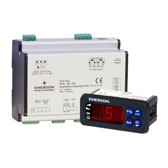
Emerson ECD-002 Instruction Sheet
Superheat controller and keypad/display unit
Hide thumbs
Also See for ECD-002:
- Operating instructions manual (7 pages) ,
- Operating instruction (25 pages) ,
- Mounting instructions (5 pages)
Table of Contents
Advertisement
Quick Links
Instruction Sheet
PA-00320
September 2008
EC3-X33 Superheat Controller and ECD-002 Keypad/Display Unit
Description
EC3-X33 is a universal superheat controller used in conjunction
with Emerson Electrical Control Valves EX4...EX8.
Safety Instructions
• Read installation instructions thoroughly. Failure to comply
can result in device failure, system damage or personal
injury.
• The product is intended for use by persons having the ap-
propriate knowledge and skills.
• Disconnect all voltages from system before installation.
• Do not operate system before all cable connections are
completed.
• Comply with local electrical regulations when wiring.
Note: The EC3-X33 series contains a lead, acid gel recharge-
able battery. The battery must NOT be disposed of with other
commercial waste. Instead, it is the user's responsibility to pass it
to a designated collection point for the safe recycling of batter-
ies (harmonized directive 98/101/EEC). For further information
contact your local environmental recycling center.
Technical data
Power supply
24VAC ±10%; 50/60Hz; 1A
Power consumption
25VA max. including EX4 ... EX8
Plug-in connector
Removable screw terminals wire size 12-20 AWG
Grounding
1/4 in spade earth connector
Protection class
IP20
Connection to ECD-002
ECC-Nxx or CAT5 cable with RJ45 connectors
Digital Inputs
0/24VAC/DC for stop/start function
NTC input
Emerson temperature sensor ECN-N60
4-20 mA Analog input
Emerson PT4-07M / PT4-18M / PT4-30M
4-20 mA Analog output
For connection to any 3
12/24VDC power supply and appropriate burden
Output alarm relay
SPDT contacts 24V AC/DC, 2 Amp inductive load
Activated:
During normal operation (no alarm condition)
Deactivated:
During alarm condition or power supply is OFF
Stepper motor output for
Maximum current 0.8A with nominal 24VDC
EX4...EX8
operating voltage
Mounting
The EC3-X33 is designed to be mounted onto a standard DIN rail.
Digital input status is dependant to operation of compressor/thermostat
Commander Operating condition
Compressor
Compressor starts
Compressor stops
Thermostat
Demand
(compressor must be ON)
No demand
www.emersonclimate.com/flowcontrols
11911 Adie Road P.O. Box 411400 St. Louis MO 63141 USA
EC3-X33 Superheat Controller
and ECD-002 Keypad/Display Unit
party controller with
rd
Digital input
Closed / 24V (Start)
Open / 0V (Stop)
Closed / 24V (Start)
Open / 0V (Stop)
Electrical Installation
• Refer to the electrical wiring diagram for electrical connections.
• Do not apply voltage to the controller before completion of wir-
ing.
• Ground the metal housing with a 1/4 in spade connector.
• Important: Keep controller and sensor wiring well separated from
mains wiring. Minimum recommended distance 1.2 in.
Warning: Use a class II category transformer for 24VAC power
supply. Do not ground the 24VAC lines. We recommend to use
individual transformers for EC3 controller(s) and for 3
controllers to avoid possible interference or grounding problems
in the power supply. Connecting any EC3 inputs to mains voltage
Preparation for Start-up
• Evacuate the entire refrigeration circuit.
Warning: Emerson Electrical Control Valves EX4...EX8 are deliv-
ered at half open position. Do not charge system before closure
of valve.
• Apply supply voltage 24V to EC3 while the digital input is 0V.
The valve will be driven to close position.
• After closure of valve, start to charge the system with refriger-
ant.
Warning: EC3 needs to be setup prior to start-up. Do not apply
24V digital input to EC3 before completion of main parameters
setting.
• Connect ECD-002 to EC3 as shown in wiring diagram with
ECC-Nxx cable or with any standard straight Cat5 cable with
two RJ45 plugs.
Setup of main parameters (need to be
checked/modified before start-up) using ECD-002
• Make sure that digital input is 0V (open). Turn the power supply
ON.
Important: Three main parameters i.e. refrigerant type (u0), pres-
sure sensor type (uP) and valve type (ut) can be set only when
digital input is open (0V) while the power supply is ON (24V).
This feature is for added safety to prevent accidental damage of
compressors and other system components.
• For easy setting of main parameters, follow the pictorial proce-
dure of "Quick start-up" on the attached individual paper.
Once the main parameters have been selected/saved the EC3
is ready for startup. All other parameters can be modified at
any time during operation or standby if it is necessary.
Start-up
Start the system and check the superheat and operating condi-
tions. The EC3-X33 is fully functional without keypad/display unit.
ECD-002 may be removed or connected at any time.
CUSTOMER SERVICE (314) 569-4666
party
rd
Advertisement
Table of Contents

Summary of Contents for Emerson ECD-002
- Page 1 The battery must NOT be disposed of with other • Connect ECD-002 to EC3 as shown in wiring diagram with commercial waste. Instead, it is the user’s responsibility to pass it ECC-Nxx cable or with any standard straight Cat5 cable with to a designated collection point for the safe recycling of batter- two RJ45 plugs.
- Page 2 Manual reset for Selecting/confirming blinking alarm codes Procedure for parameters modification using ECD-002 The parameters can be accessed via the 4-button keypad. The con- figuration parameters are protected by a numerical password. The default password is “12”. To select the parameter configuration: •...
- Page 3 No data to display eters be shown again. The display will show an “—” at start up and when no data is sent to ECD-002 Checking system operating conditions The data to be permanently shown on the display can be selected by the user ┌┘...
- Page 4 Quick Start Up EC3-X33 & ECD-002 EC3-X33 24 V AC 5 sec. 0 = R22 1 = R134a 2 = R507 1 = EX4 3 = R404A 2 = EX5 4 = R407C 3 = EX6 R 410A 5 = R410A...


Need help?
Do you have a question about the ECD-002 and is the answer not in the manual?
Questions and answers