Advertisement
Lumnia Ultimate US - Instruction Manual
+
Includes Lumnia
Encapsulation Module
This manual is based on the latest information and is provided subject to alteration.
We reserve the right to change the construction and/or confi guration of the product
and versions at any time without obligation.
All rights reserved. No part of this document may be reproduced, stored in a database or any other retrieval
system, or published, in any form or way, electronically, mechanically, digitally per photo print or microfi lm or
any other way without written permission from the author.
Advertisement
Table of Contents

Related Manuals for Rentokil Lumnia Ultimate


Summary of Contents for Rentokil Lumnia Ultimate
- Page 1 Lumnia Ultimate US - Instruction Manual Includes Lumnia Encapsulation Module This manual is based on the latest information and is provided subject to alteration. We reserve the right to change the construction and/or confi guration of the product and versions at any time without obligation.
- Page 2 1. Safety Warning The lamps in this unit produce ultraviolet (UV) light, which can SAVE THESE cause skin or eye damage if viewed directly for a long period. INSTRUCTIONS Only fit the correct type of UV lamps in the unit. The unit shall be installed and serviced by individuals with appropriate qualifications and/or experience in accordance with national regulations in the country of operation and...
-
Page 3: Equipment For Installation
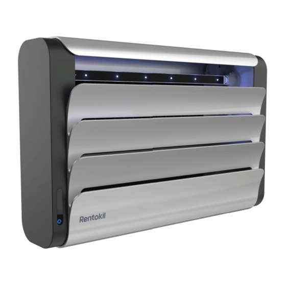
2. Introduction The Lumnia Ultimate unit uses three ultra-violet LED driven lamps that attract fl ying insects that are then captured on a replaceable glue board or encapsulation module. The modular design of this unit allows for both. The Ultimate product comes as a glue board monitoring device which can be upgraded to a control device by adding the Lumnia + encapsulation module. -
Page 4: Installation Instructions
4. Installation Instructions: Connecting the Power Source DANGER: You must NOT connect the unit into a lighting circuit. WARNING: You must connect the power cable to a standard power socket. DANGER: SERVICING OF DOUBLE-INSULATED APPLIANCES In a double-insulated appliance, two systems of insulation are provided instead of grounding. -
Page 5: Positioning The Unit
5. Positioning the Unit Position the unit on a suitable wall at a minimum height of 1.74 metres to the bottom of the unit. Figure 1 illustrates the suggested mounting height and illustrates what happens during service mode. Position the unit as far as possible from sources of ambient light. -
Page 6: Positioning Guide
For safety reasons, the unit contains a micro switches that disables the UV lamps if you open the Front Louvre or if the products service mode (Slide) is activated. See section 7 and 8. Figure 2 indicates the size and space considerations for louvre cover opening sweeps at 90°. -
Page 7: Installation Preparation
7. Installation Preparation 1.74M Ø6mm... - Page 8 Opening the Louvres Mounting Lumnia NOTE: Remove lamps before screwing See Section 12 for more details on lamp removal SECURE WITH ALL 4X SCREWS...
- Page 9 8. Activating the Slide Mechanism 9. Preparing the Glue Board Fold Flex Remove Liner...
- Page 10 10. Installing the Glue Board 11. Removing the Glue Board...
- Page 11 12. Removing and Replacing the UV - LED Lamps For lamp identifi cation refer to reference number on Lamp. Only Lamps specifi ed in Section 20 - Accessories and Spares to be used with this product. Do not touch LED when servicing, maintaining or cleaning the lamps. Removing UV - LED Lamps 2.
-
Page 12: User Interface Settings
13. User Interface Settings Functions for use with Lumnia ONLY: See Section 17 for Lumnia User Interface Mode Button I = Low II = Med III = High A A A C C C A = Adaptive Low* B = Adaptive Med* C = Adaptive High* * Adaptive Mode: The Adaptive light setting reduces the light output when light levels are below... - Page 13 14. Lumnia Encapsulation Module Your Lumnia Ultimate can be turned from a monitoring device to a control device in areas where fl y infestations may occur. A motorised Encapsulation Module can be purchased to use with your Lumnia. Roll included...
- Page 14 16. Loading Lumnia Encapsulation...
- Page 15 17. Lumnia Encapsulation Interface Settings See Section 14 for fi tting the Lumnia+ Module The interface is activated when the Module is inserted Lumnia User Interface Glue Roll Manual Override Glue Roll Service Day Setting 30 day setting rolls on a clean glue surface every 24 hours Mode Button See Section 13 for Mode Setting User Interface...
- Page 16 18. Glue Roll Manual Override GREEN: OPERATIONAL RED: FAULT NOTE: Counter for Lumnia Encapsulation Module resets when removed from Lumnia. Important that module is removed for a new Glue Roll.
- Page 17 19. Servicing: Replacing the Glue Roll Part Part Part Part Part Reuse parts A - E above to create the new Roll Assemblies below New Roll With emboss Without emboss Part Part Part Part Part...
-
Page 18: Accessories And Spares
Rentokil can accept no liability whatsoever for any loss or damage arising from the product being... -
Page 19: Specification
• Boxed Unit 8.0 kg (boxed) • Unit including Lamps 6.6 kg & Glueboard • Lumnia+ Encapsulation 1.35 kg (unit) Module Lumnia+ Encapsulation Module 24V DC Refer to Lumnia Ultimate Manual for full installation instructions, scan the QR code or visit: www.rentokil.com/manuals... - Page 20 Rentokil reserve the right to alter the specification or design without prior notice. Rentokil cannot accept any liability for any loss or damage arising from the use of any information contained within this manual, or from any incorrect use of the product described herein.
Need help?
Do you have a question about the Lumnia Ultimate and is the answer not in the manual?
Questions and answers