Table of Contents
Advertisement
Advertisement
Table of Contents

Subscribe to Our Youtube Channel
Related Manuals for Airzone AZVAFR Series


Summary of Contents for Airzone AZVAFR Series
- Page 1 Installation´s Manual P d r a o b p il C u N e g a r e b m...
-
Page 3: Table Of Contents
Communication gateway (AZVAFGTXXX) ...................................9 0-10 V Fancoil control gateway (AZVAFGTF10) ..............................10 5-Relay Fancoil control gateway (AZVAFGTF5R) ..............................10 Webserver Airzone cloud Ethernet/WiFi (AZVAFWSCLOUD [C/R]) ......................... 10 Bacnet integration gateway (AZVAFBACNETG) ..............................11 10 KOHM NTC thermistor (AZVAF10KPROBE) ................................. 11 Additional 12 V power supply (AZVAFPOWER) ............................... - Page 4 0-10 V Fancoil control gateway (AZVAFGTF10) ..............................26 Assembly ............................................26 Connection ............................................27 5-Relay Fancoil control gateway (AZVAFGTF5R) ..............................28 Assembly ............................................28 Connection ............................................28 Ethernet/WiFi cloud Webserver (AZVAFWSCLOUD [C/R]) ..........................30 Assembly ............................................30 Connection ............................................30 Configuration ..........................................
- Page 5 Navigation Trees ............................................61 Blueface Thermostat Navigation Tree ..................................61 Think Thermostat Navigation Tree ....................................62...
-
Page 6: Precautions And Environmental Policy
PRECAUTIONS AND ENVIRONMENTAL POLICY PRECAUTIONS For your security, and to protect the devices, follow these instructions: • Do not manipulate the system with wet or damp hands. • Disconnect the power supply before making any connections. • Take care not to cause a short circuit in any of the system connections. ENVIRONMENTAL POLICY Do not dispose of this equipment in the household waste. -
Page 7: System Elements
Wired/wireless communication with zone thermostat. Powered through system Airzone connection bus. Functionalities: • Input for detection of open windows. • Input for detection of presence. • Probe input. • Remote probe function and distributed probe function. -
Page 8: Wired/Wireless Zone Module With Xxx Communication (Azvafzmxxx [C/R])
Demand Relay of Boiler. • Identified by means of a micro-switch. BLUEFACE PRINCIPAL CONTROLLER (AZVAFBLUEFACEC) Color graphic interface with capacitive screen for controlling zones in Airzone systems. Powered by zone module. Finished in steel and glass. Functionalities: • Available in English, French and Spanish. -
Page 9: Wired/Wireless Think Controller (Azvafthink [C/R])
• Room temperature and relative humidity reading. COMMUNICATION GATEWAY (AZVAFGT XXX) Element that integrates the functioning of the AC units and Airzone zoning systems, enhancing the performance of the installation: • ON/OFF depending on the number of zones in demand. -
Page 10: Fancoil Control Gateway (Azvafgtf10)
Automatic speed selection according to the number of zones on demand. WEBSERVER AIRZONE CLOUD ETHERNET/WIFI (AZVAFWSCLOUD [C/R]) Webserver for controlling Airzone systems through Airzone Cloud platform. Accessible through browser or App (available for IOS and Android). Connected to router via Ethernet (AZVAFWSCLOUDC) or WiFi (AZVAFWSCLOUDR). Powered through automation bus. -
Page 11: Bacnet Integration Gateway (Azvafbacnetg)
BACNET INTEGRATION GATEWAY (AZVAFBACNETG) Integration gateway for controlling Airzone installations through BACnet platform. Connected to router via Ethernet. Power supplied through the control board automation bus. Functionalities: • One BACnet gateway per system. • Status of window contact and presence contact of each zone. -
Page 12: General Requirements
GENERAL REQUIREMENTS Strictly follow the directions outlined in this manual: • This system must be installed by a qualified technician. • Make all the connections with total absence of power. • Set and connect the elements in accordance with the electronic regulations in force. •... -
Page 13: Introduction
Locate all the elements and perform the connection (See section Zone and Control Modules connection with the Airzone VAF Control board. Connect the zone modules of the system to any of the 3 Airzone connection bus terminals. Use the proper cable: shielded twisted pair 4 wired: 2x0.22 mm 2x0.5mm... - Page 14 Control Board (follow the steps shown on the Assembly section). All Airzone systems must be connected to internet to offer technical support. It is only necessary to connect one Webserver Cloud per installation (control of up to 32 systems), for BACnet integration gateway, one per system.
-
Page 15: Assembly And Connection
Fig. 2 Airzone Connection Bus connectors The Airzone Connection Bus allows you to connect all the internal components that are independent from the main board to control up to 10 zones. These are the gateways that can be connected: Wired/Wireless intelligent round damper (AZVAFDAMPERxxx [C/R]). - Page 16 Fig. 5 Automation bus connector The automation bus allows you to interconnect multiple systems in order to control them through Airzone control peripherals or to integrate them into a superior control network. The elements to connect to this bus are: Ethernet/WiFi Cloud Webserver (AZVAFWSCLOUD [C/R]).
- Page 17 Protection temperature probe connector It measures the outdoor temperature through an external probe. We recommend the use of this probe when using electromechanical units or NON-Inverter units (when it is necessary to control the return temperature of the units). Auxiliary heat outputs The system includes auxiliary heat, connect the auxiliary heat relays of the VAF Control board to the elements to control.
-
Page 18: Wired/Wireless Intelligent Round Damper (Azvafdamperxx [C/R])
Window contact Note: Use a shielded twisted pair to connect the window contact. The Intelligent round damper is a device that is connected to the Airzone Connection Bus of the control board (Fig. 11). Fig. 11 It has a 5-pin terminal to connect it to the Airzone Connection Bus of the main board. Use the proper cable: shielded twisted pair 4 wired: 2x0.22 mm... -
Page 19: Flow Regulation
• Control by occupancy: When the occupancy sensor connected to the module indicates that the zone is unoccupied, the system waits for 5 minutes to confirm it is actually empty. After this period of time, the zone is set to Timer Mode and it turns off after 90 minutes. -
Page 20: Wired/Wireless Only Radiant Zone Module (Azvafzmrad [C/R])
Fig. 15 Connection The Only Radiant Zone Module is a device that is connected to the Airzone connection bus of the control board (Fig. 16). Fig. 16 It has a 5-pin terminal to connect it to the Airzone Connection Bus of the main board. Use the proper cable: shielded twisted pair 4 wired: 2x0.22 mm... -
Page 21: Wired/Wireless Zone Module With Xxx Communication (Azvafzmxxx [C/R])
Window contact Presence contact (Only AZVAFZMxxxC) Thermostat Connection Airzone Connection Bus Note: Use a shielded twisted pair to connect the window contact. Fig. 19 Assembly The module is mounted on DIN rail (Fig. 20) or on wall (Fig. 21). It must be placed and mounted in accordance with the current... -
Page 22: Connection
Note: To remove the module on DIN rail, pull the tab down to release it. Connection The gateway module is a device that is connected to the Airzone connection bus of the control board (Fig. 34). Fig. 22 It has a 5-pin terminal to connect it to the Airzone Connection Bus of the main board. Use the proper cable: shielded twisted pair 4 wired: 2x0.22 mm... -
Page 23: Relay Radiant Heat Control Module (Azvaf5Outputs)
Description Zone relay Pump control relay Boiler control relay Airzone connection bus Fig. 25 Assembly The module is mounted on DIN rail (Fig. 26) or on wall (Fig. 27). It must be placed and mounted in accordance with the current electrotechnical regulations. -
Page 24: Connection
WIRED THERMOSTATS (AZVAFBLUEFACEC / AZVAFTHINKC / AZVAFLITEC) Assembly Airzone thermostats are mounted on the wall through a support. It is recommended not to locate it more than 40 meters away from the control board. To fix it to the wall, follow these steps (Fig. 30): •... -
Page 25: Connection
Connection Airzone thermostats are connected to the zone module to be controlled. Attach the wires with the terminal screws following the color code (Fig. 31). Important: Use the provided tool to press in the locking tabs (Fig. 32). Fig. 31 Fig. -
Page 26: Fancoil Control Gateway (Azvafgtf10)
Fig. 36 Important: We recommend using of top-brand batteries. Using low-quality batteries may reduce the duration of use. Remember to deposit the old battery into an appropriate recycling point. 0-10 V FANCOIL CONTROL GATEWAY (AZVAFGTF10) Meaning Power supply AC unit bus OUT 1 Cooling air demand OUT 2... -
Page 27: Connection
Connection The 0-10 V control gateway is connected to the AC unit bus of the main board (Fig. 40 and 41). Wiring diagram, 2-pipe installation Fig.40 Wiring diagram, 4-pipe installation Fig. 41 Control relay specs: I = 10 A at 110/230 Vac, voltage-free. Note that to control elements with a greater power, it is recommended to use contactors in accordance with the power required. -
Page 28: 5-Relay Fancoil Control Gateway (Azvafgtf5R)
5-RELAY FANCOIL CONTROL GATEWAY (AZVAFGTF5R) Description Power supply AC unit bus Cooling air demand Speed 1 V1-O Speed 2 V2-O V3-O Speed 3 Heating air demand Status LEDs Fig. 44 Assembly The 5-Relay Fancoil control gateway is mounted on DIN rail (Fig. 45) or on wall (Fig. 46). This module is externally powered at 110/230 Vac. - Page 29 Wiring diagram, 4-pipe installation Fig. 48 Control relay specs: I = 10 A at 110/230 Vac, voltage-free. Note that to control elements with a greater power, it is recommended to use contactors in accordance with the power required. It has a 5-pin terminal to connect it to the AC unit bus of the main board. Use the proper cable: shielded twisted pair 2 wired: 2x0.22 mm (AWG 24 2 wired).
-
Page 30: Ethernet/Wifi Cloud Webserver (Azvafwscloud [C/R])
AZVAFWSCLOUDR Automation bus input Fig. 51 All Airzone systems must be connected to internet to offer technical support. It is only necessary to connect one Webserver Cloud per installation (control of up to 32 systems). Assembly The Webserver is integrated into the automation bus of the Control board (Fig. -
Page 31: Configuration
Automation bus output Automation bus input Fig. 54 All Airzone systems must be connected to internet to offer technical support. It is only necessary to connect one BACnet integration gateway per system. Assembly The BACnet integration gateway is integrated into the automation bus of the main board (Fig. -
Page 32: Assembly And Connection Evaluation
Fig. 56 process. Start the radio channel search, to do so, press Airzone to start the search. The thermostat will display the different wireless zone modules found, with the signal level of each one of them. Select the range is... - Page 33 IMPORTANT: Before, selecting the zone module which will be associated with the thermostat, check that this module is the desired one. If this module is not the correct one, use the control bar to select another module and check again. IMPORTANT: The thermostat will display first the wireless zone modules which are closer to it.
- Page 34 Think Important: In Think thermostats, use to confirm and to return to the previous screen or menu.
-
Page 35: Lite Thermostats
LITE THERMOSTATS To configure a Lite thermostat, follow these steps: Wired Lite thermostat Perform all the appropriate connections. Connect the thermostat. Press the LED to confirm the association. The number of the zone which associates with the thermostat is the lowest free available number. If the association is correct, the LED will flash green 5 times. -
Page 36: Lite Thermostat Reset
Insert the battery to supply the thermostat. Press the LED to begin the wireless search. The LED will blink in green. IMPORTANT: The thermostat will display first the wireless zone modules which are closer to it. Remember to configure this thermostat near the wireless zone module to associate for greater comfort. will show the signal level of this module: Low signal range level (It is not recommended to perform the association). -
Page 37: User And Zone Settings
USER AND ZONE SETTINGS BLUEFACE THERMOSTAT Operation mode Airflow/Fan speed User mode Current zone/ Zone Current Room navigation menu Temperature/ Relative humidity Current Set Point Zone demand On/Off Local ventilation Time schedule Zone settings programming User settings User Settings Press to access the menu. -
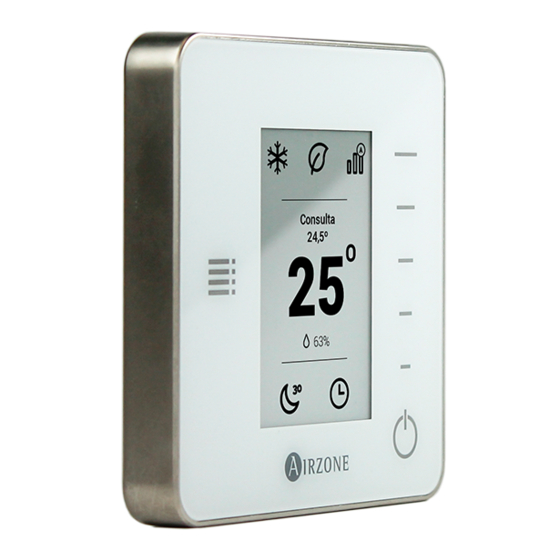
Page 38: Think Thermostat
* Available based on the installation and system setting. Lite Settings. To save energy, enables to configure the wired Airzone Lite to switch off after a few second. Note: To access the Lite settings, go to a zone controlled by a Lite thermostat through the zone navigation menu. - Page 39 Emergency Heat. This mode activates the Auxiliary Heat to provide heated air in case of a mechanical failure in the system. Note: This mode is only visible when the installation includes an auxiliary heating device. User Mode. This parameter is only available when the Think thermostat is configured as main, the available modes are: Comfort.
- Page 40 Timer. It is an auto power-off timer of the zone. Off. Timer is not activated. 30. It activates the timing and switches off the zone after 30 minutes. 60. It activates the timing and switches off the zone after 60 minutes. 90.
-
Page 41: Advanced Settings
ADVANCED SETTINGS ADVANCED SETTINGS BLUEFACE THERMOSTAT To access the advanced configuration menu, follow the next steps: Press and hold From this menu you can control both the zone parameters and the system parameters. System settings • System ID. Defines the number of the system within your installation. •... - Page 42 Port: 47808 IP Address: DHCP • (only available in installations with Airzone VAF 10 KOhm NTC thermistor). Supply temperature This option allows the system demand to be ignored if the supply temperature exceeds a certain limit. The selectable heating cut out...
-
Page 43: Zone Settings
• Radio channel. It activates/deactivates the radio channel of the system. • (only available for main thermostat) Reset system . Resets the system and returns to factory settings. To reconfigure the thermostats, please check Initial setup . Wait 60 seconds until the system restarts before connecting again. Zone settings •... -
Page 44: Advanced Settings Think Thermostat
ADVANCED SETTINGS THINK THERMOSTAT To access the advanced configuration menu, follow the next steps: Press once Press and hold Press and hold Important: In Think thermostats, press to confirm and to return to the previous menu/screen. • Linked zones. It displays and allows you to select the control outputs associated with the thermostat. •... -
Page 45: Self-Diagnose
SELF-DIAGNOSE CONTROL BOARD (AZVAFRXXXX) Airzone control boards have integrated LEDs that detect unusual operations. Fig. 57 Meaning Data reception from automation bus Blinking Green Data transmission from automation bus Blinking Control board activity Blinking Green Data transmission from Airzone Connection Bus... -
Page 46: Wired/Wireless Intelligent Round Damper And Wired/Wireless Only Radiant Zone Module (Azvafdamperxxx [C/R] And Azvafzmrad [C/R])
Steady Data reception from thermostat Blinking Green Data transmission from thermostat Blinking Data reception from Airzone connection bus Blinking Green Data transmission from Airzone connection bus Blinking WIRED/WIRELESS ZONE MODULE WITH XXX COMMUNICATION (AZVAFZM XXX [C/R]) The zone modules have integrated LEDs that detect unusual operations. -
Page 47: Relay Radiant Heat Control Module (Azvaf5Outputs)
Meaning Power supply Steady Data transmission from thermostat Blinking Data reception from thermostat Blinking Green Data transmission from Airzone connection bus Blinking Data reception from Airzone connection bus Blinking Green Data transmission from gateway Blinking Data reception from gateway Blinking... -
Page 48: Blueface And Think Thermostats (Azvafbluefacec / Azvafthink [C/R])
BLUEFACE AND THINK THERMOSTATS (AZVAFBLUEFACEC / AZVAFTHINK [C/R]) Blueface and Think Thermostat Warnings Thermostat displays all the system warnings on the screensaver. If there is any error, it will be displayed on the screensaver, on the main screen and on tio , inside the User settings menu. - Page 49 AZVAFDAMPERxxC / AZVAFZMRADC Fig. 61 AZVAFZMxxxC Fig. 62 Error 1: Communication error between wireless thermostat and zone module (AZVAFDAMPERxxR / AZVAFZMRADR / AZVAFZMxxxR) This incident blocks the control of the zone. To solve this incident check: Thermostat status: Check the signal range of the thermostat with the module through the Information parameter (see Advanced settings, system settings section ) or approach the thermostat to the module if the thermostat recovers the...
- Page 50 This incident blocks the control of the zone. Check this error is not common to all thermostats. If so, verify the proper operation of the main board. To solve this incident check: Control board status: Correctly powered. Control board status: Airzone Connection Bus LEDs are operating properly. Connection: Verify the polarity of the control board and thermostat connectors.
- Page 51 The system detects that the motorized element has an abnormality and blocks the opening-closing movement. Disconnect and connect the Airzone connection bus terminal and check if the error disappears, otherwise, proceed to the replacement of the device or sent it for repair.
- Page 52 Fig. 67 Error 5: Temperature probe - Open circuit The zone ceases to measure the room temperature; therefore, the zone cannot generate demand. Proceed to replace it of the device or sent it for repair (check if it is produced b probe output of the zone module).
- Page 53 Verify if the Air unit is powered. To do this, check the thermostat of the AC unit is ON. Verify the AC unit operates properly by itself. To do this, disconnect the A/C unit Airzone system and select the unit from the thermostat from the A/C unit.
- Page 54 The device cannot be controlled by the system. To solve this incident check: Status of the module: Correctly powered. Status of the module and the control board: Airzone connection bus LEDs are operating properly. Connection: Check the polarity of the connectors of the control board and the module.
-
Page 55: Lite Thermostats (Azvaflite [C/R])
LITE THERMOSTATS (AZVAFLITE [C/R]) Lite thermostats incorporate LEDs that detect malfunctioning. Status LED blinking purple quickly: Wired Lite Thermostat- Zone module communication error (AZVAFDAMPERxxC / AZVAFZMRADC / AZVAFZMxxxC) This incident blocks the control of the zone. To solve this incident check: Connection: Check the polarity of the connectors of the module and the thermostat. - Page 56 AZVAFZMxxxC Fig. 74 Status LED blinking purple quickly: Wireless Lite Thermostat- Zone Module communication error (AZVAFDAMPERxxR / AZVAFZMRADR / AZVAFZMxxxR) This incident blocks the control of the zone. To solve this incident check: Thermostat status: Check the signal range of the thermostat with the module through the Information parameter from remote zones or approach the thermostat to the module if the thermostat recovers the communication, it is necessary to relocate it as it was out of range.
- Page 57 To solve this incident check: Control board status: Correctly powered. Control board status: Airzone Connection Bus LEDs are operating properly. Connection: Verify the polarity of the control board and thermostat connectors. Wiring: Check that the voltage between the poles (A /-) and (B/-) is about 0.65 Vdc.
-
Page 58: Communication Gateways (Azvafgtxxx)
Verify the gateway is properly connected to the AC unit port of the control board. Microprocessor operation LED D2: Not blinking • Contact the Airzone after-sales department, the microcontroller does not operate properly. Communication LEDs D3 and D4: Not blinking •... -
Page 59: 5-Relay Fancoil Control Gateway (Azvafgtf5R)
Blinking Gateway performance Blinking Green Power supply Steady LEDs of relay state Blinking Green ETHERNET/WIFI CLOUD WEBSERVER (AZVAFWSCLOUD [C/R]) Airzone Cloud Webservers incorporate LEDs that detect malfunctioning. AZVAFWSCLOUDC AZVAFWSCLOUDR Fig. 80 Meaning Ethernet connected Green Blinking Ethernet activity Blinking Yellow / Red... -
Page 60: Bacnet Integration Gateway (Azvafbacnetg)
BACNET INTEGRATION GATEWAY (AZVAFBACNETG) BACnet integration gateways incorporate LEDs that detect malfunctions. Fig. 81 Meaning Ethernet connected Blinking Green Ethernet activity Blinking Yellow / Red Data transmission from automation Blinking Data reception from automation bus Blinking Green Microswitch performance Blinking Green Connected to the Internet Blinking... - Page 61 NAVIGATION TREES BLUEFACE THERMOSTAT NAVIGATION TREE...
- Page 62 THINK THERMOSTAT NAVIGATION TREE Remember: Use to confirm and for going back if browsing submenus.
- Page 63 Parque Tecnológico de Andalucía C/ Marie Curie, 21 29590 Campanillas Málaga - España Phone: +34 902 400 445 Fax: +34 902 400 446 http://www.myzone.airzoneusa.com...
Need help?
Do you have a question about the AZVAFR Series and is the answer not in the manual?
Questions and answers