Advertisement
Quick Links
Table of Contents
TV/Display Specifi cations. . . . . . . . . . . . . . . . . . . . . . . . . . . . . . . . . . . . . . . . . . . . . . 1
Safety Hazard Symbol Review. . . . . . . . . . . . . . . . . . . . . . . . . . . . . . . . . . . . . . . . . . 2
Components . . . . . . . . . . . . . . . . . . . . . . . . . . . . . . . . . . . . . . . . . . . . . . . . . . . . . . . . 2
Tools . . . . . . . . . . . . . . . . . . . . . . . . . . . . . . . . . . . . . . . . . . . . . . . . . . . . . . . . . . . . . . 3
Determine mounting location . . . . . . . . . . . . . . . . . . . . . . . . . . . . . . . . . . . . . . . . . . . 4
Mount Glide to wall:
Option A: wood stud walls. . . . . . . . . . . . . . . . . . . . . . . . . . . . . . . . . . . . . . . . . . . . 5
Option B: solid concrete walls. . . . . . . . . . . . . . . . . . . . . . . . . . . . . . . . . . . . . . . . . 6
Attach TV/Display to Glide . . . . . . . . . . . . . . . . . . . . . . . . . . . . . . . . . . . . . . . . . . . . . 7
Option A: no VESA adapter needed . . . . . . . . . . . . . . . . . . . . . . . . . . . . . . . . . . . . 9
Option B, C, D: with VESA adapters . . . . . . . . . . . . . . . . . . . . . . . . . . . . . . . . . . . 9
Quick Release . . . . . . . . . . . . . . . . . . . . . . . . . . . . . . . . . . . . . . . . . . . . . . . . . . . . . 12
Test Range of Motion . . . . . . . . . . . . . . . . . . . . . . . . . . . . . . . . . . . . . . . . . . . . . . . . 13
Adjust according to applied load and desired user force . . . . . . . . . . . . . . . . . . . . . 13
www.omnimount.com
User's Guide - English
Guía del usuario - Español
Manuel de l'utilisateur - Français
Gebruikersgids - Nederlands
Benutzerhandbuch - Deutsch
Guida per l'utente - Italiano
Användarhandbok - svenska
ユーザーガイ ド : 日本語
用户指南 : 汉语
888-61-054-W-00 rev. E • 10/13
Screen
Capacity
27"- 42"
12 - 30 lbs
(5.5 - 13.6 kg)
Lift
Rotation
Yes
≥10"
(25.4mm)
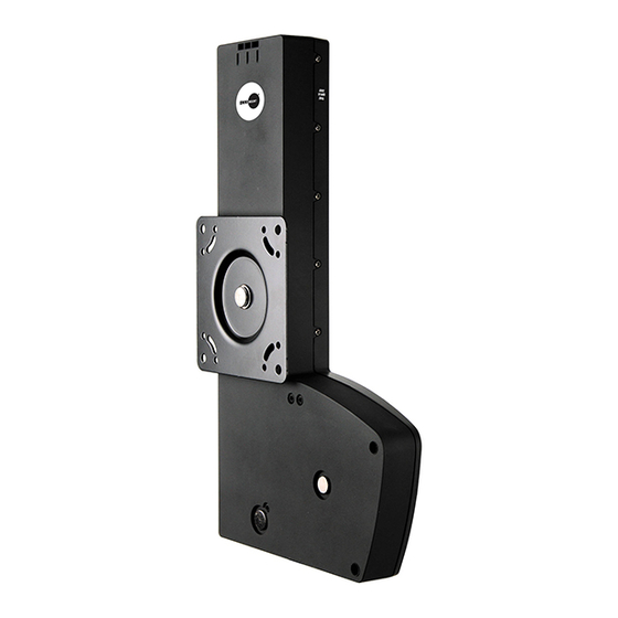
Lift30
User's Guide
OM1100604
VESA
100 x 100
100 x 200
200 x 200
200 x 100
300 x 300
400 x 400
1 of 14
Advertisement

Related Manuals for Omnimount Lift30


Summary of Contents for Omnimount Lift30
- Page 1 Lift30 User's Guide OM1100604 Screen Capacity Lift Rotation VESA 27”- 42” 12 - 30 lbs 100 x 100 ≥10” (5.5 - 13.6 kg) (25.4mm) 100 x 200 200 x 200 200 x 100 300 x 300 400 x 400 Table of Contents TV/Display Specifi...
- Page 2 Hazard Symbols Symbol Signal Word Level of Hazard Review A NOTE indicates important information that helps you NOTE make better use of this product. These symbols alert users of a safety condition that demands attention. All users should be able A CAUTION indicates either potential damage to to recognize and understand the signifi...
-
Page 3: Tools Needed
Tools Needed 10 mm 1/8” 3/8” 3-1/8” 3-1/8” 80mm 80mm 3 of 14 888-61-054-W-00 rev. E • 10/13... - Page 4 Determine mounting location. CAUTION: Before proceeding with this installation consult your TV/large display product guide for manufacturer recommendations on choosing a mounting location that will ensure optimum TV/large display performance. Location considerations might include: TV/large display height and viewing angle - based on height and distance of seating, room dimensions and size of TV/large display; access to power outlets;...
- Page 5 Mount bracket to wall Option A: wood stud walls 1/8” 3-1/8” 80mm M6 x 70mm NOTE: make sure extension bracket is level before tightening bolts. Go to Step 3 on the page 7. 10mm 5 of 14 888-61-054-W-00 rev. E • 10/13...
- Page 6 Mount bracket to wall 3/8” WARNING: Mounting holes must be at least 3-1/8” (80mm) deep and must be located within solid concrete, not mortar or cov- ering material. If you drill into an area of concrete that is not solid, reposition mounting holes until both anchors can be fully inserted into solid concrete! 3-1/8”...
- Page 7 Ensure the bracket is level. Determine TV/large display mount fasteners NOTE: If a stand is already attached to your TV/large display, remove it according to TV/large display manu- facturer directions. Place the display on a clean, fl at, padded surface or, if you prefer, lean the TV/large display against a stable, vertical surface.
- Page 8 Determine if VESA adapters are needed between TV/display and Glide LD Check the shape and size of your TV/large display mounting hole confi guration against the VESA con- fi gurations shown below. Choose VESA option that matches and continue to Step 6 on the next page. TV/large display Mounting Hole Confi...
- Page 9 Option A: Attach TV/large display to the Glide LD using fasteners determined in step 4 and spacers if needed Continue to Step 7 on page 12. Options B, C, and D Attach VESA Adapters to Glide. Step 6 details continued on the next page.
- Page 10 VESA Mounting Hole Confi gurations Option B Option C Option D Rotate VESA plate to access mounting holes. M4 x 6mm Step 6 continued on the next page. 10 of 14 888-61-054-W-00 rev. E • 10/13...
- Page 11 Options B, C, and D (cont.) Attach TV/large display to the Glide LD using fasteners determined in step 4 and spacers if needed 11 of 14 888-61-054-W-00 rev. E • 10/13...
- Page 12 Mount Lift30 (with attached TV/large display) to bracket on wall. Quick-release instructions: to remove from the wall, pull down on the strap below the extension. 12 of 14 888-61-054-W-00 rev. E • 10/13...
- Page 13 Adjustment Step Important! You will need to adjust this product after installation is complete. Make sure all your equipment is properly installed on the product before attempting adjustments. This product should move smoothly and easily through the full range of motion and stay where you set it. If movements are too easy or diffi cult or if product does not stay in desired positions, follow the adjustment instructions to create smooth and easy movements.
- Page 14 All trademarks are the property of their respective companies. OmniMount is a registered trademark of OmniMount, Inc. © 2012 Disclaimer – OmniMount, Inc. has extended every eff ort to ensure to accuracy and completeness of this manual. However, OmniMount, Inc. does not claim that the information covers all installation or operational variables.
Need help?
Do you have a question about the Lift30 and is the answer not in the manual?
Questions and answers