
Related Manuals for Prolon T1000 Series


Summary of Contents for Prolon T1000 Series
- Page 1 HARDWARE GUIDE Digital Sensor - T1000 Series Specifications and Operational Guide www.proloncontrols.com | info@proloncontrols.com 17 510, rue Charles, Suite 100, Mirabel, QC, J7J 1X9 REV. 6.2.3 PL-HRDW-T1000-F-EN...
-
Page 2: Table Of Contents
Table of Contents General Information ..........................4 Description ..................................4 Part Number Selection ..............................4 Installation ............................5 Power and Communication ......................... 6 Auxiliary Analog Input ..............................6 Operation ............................. 7 Hint Display ..................................7 Changing the Setpoint ........................8 Schedule Override .......................... - Page 3 Table of Figures Figure 1 - Opening Tab ..............................5 Figure 2 - Terminal Block Pinout ............................ 5 Figure 3 - Terminal Block ..............................6 Figure 5 - Connecting the Auxiliary Input ........................6 Figure 4 - RJ45 Pinout ............................... 6 Figure 7 - Touch Pad Feedback............................
-
Page 4: General Information
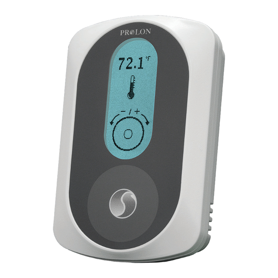
General Information Description The T1000 digital sensors are designed for operation in conjunction with the ProLon VAV or HPS controllers, to which they provide zone temperature, setpoint and occupancy override information. The T1000 digital sensors also provide an access point from which to visualize and configure any parameter on the connected VAV controller through an on-screen menu system. -
Page 5: Installation
Installation 1. Open casing to remove back cover by pushing on the tab located underneath the thermostat. (Figure 1) 2. Pull wire(s) through central hole of back cover. 3. Screw in the back cover to the wall. 4. Connect wires: •... -
Page 6: Power And Communication
Power and Communication The T1000 is typically powered by the same controller it is communicating with. It has two different connector types available for your choice of preferred wiring method. • The first is a 4-pin, screw-type terminal block suitable for a 4 wire connection •... -
Page 7: Operation
Operation The T1000 is controlled using the circular touch pad on the bottom half of the thermostat. The touch pad uses capacitive sensing technology to detect finger proximity. There are no moving parts to push or rotate. The T1000 is controlled using simple scrolling, tapping or holding motions, performed around the circle of the touch pad. -
Page 8: Changing The Setpoint
Changing the Setpoint Home Screen Setpoint Screen Heat SP Scroll or tap (any direction) Cool SP View current zone temperature Tap anywhere Adjust your setpoint (or simply wait) by scrolling clockwise return to or counterckwise Home Screen Schedule Override First, go to the Setpoint Screen. The sun icon is displayed when overridden... -
Page 9: Navigating Menus
Navigating Menus From the Home Screen. 75.1 75.1 Hold left Hold right for 8 sec for 5 sec Con guration Options and Menu Visualisation Menu Menu Configure SCROLL clockwise or counterclockwise Active Menu to navigate through the current menu level Tap here to Tap here to go BACK... -
Page 10: Menu Structure
Menu Structure The T1000 has two menu systems: The first is dedicated to the general options of the T1000 thermostat as well as visualization of the status of the controller to which it is connected. The second menu system is dedicated entirely to the configuration settings of the controller to which it is connected. These menu structures are outlined below. -
Page 11: Vav Controller: Visualisation Displays
VAV Controller: Visualisation Displays Zone Temperature Active Zone Setpoints Occupancy Status Status 1 Zone Demand Damper Position Air Flow Reading Status of all Outputs Visualize Status 2 Supply Air Temperature Outside Air Temperature Discharge Air Temperature Air Flow SP Status 3 Radiant Flow Cycle % CO Reading VAV Controller: Configuration Menus (Top Level) -
Page 12: Vav Controller: Configuration Menus - Temperature
VAV Controller: Configuration Menus - Temperature Deadband PropBand PI Control Cool Integral Heat Integral Min Heat Max Heat SP Limits Min Cool Max Cool Heat O set Cool O set Temperature Unocc Mode Heat SP Lim Cool SP Lim Heat Scale Lim Scale Lim Cool Scale Lim Enable... -
Page 13: Vav Controller: Configuration Menus - Pressure
VAV Controller: Configuration Menus - Pressure Min Vent SP Max Vent SP Flow SP Min Vent Heat SP Min Vent CO Diameter Pressure Duct Setup K Factor Sensor Flow Di Sensitivity Damper Speed VAV Controller: Configuration Menus - Outputs Duct Heater Radiant Floor Special Function FPB Output... -
Page 14: Vav Controller: Configuration Menus - Radiant Floor
VAV Controller: Configuration Menus - Radiant Floor Max Slab Temp Limits Min Slab Temp Unoccupied Min Slab Temp Mode Radiant Floor Proportional PI Loop Integral Cycle Length Setup Outside Cuto Calibration VAV Controller: Configuration Menus - Other Unocc Over Time Timing Morn WarmUp Max Receive Time... -
Page 15: Vav Controller: Configuration Menus - Calibration
VAV Controller: Configuration Menus - Calibration Zone Temperature Supply Calibration O set Ventilation Corr Factor Auto-Calibrate REV. 6.2.3 / PL-HRDW-T1000-F-EN... -
Page 16: Vav Controller: Configuration Menus - Network
VAV Controller: Configuration Menus - Network Math Enable Math 1 Source Math 1 Group Math 2 Source Math 2 Group Math 3 Source Math 3 Group Math 4 Source Math 4 Group Math 5 Source Math 5 Group Poll Rate List Refresh Math Functions Unoccupied Mode... -
Page 17: Technical Specifications
Mounting: Standard electrical box 2" x 4" Certification: FCC Part 15: 2012 class B The performance specifications are nominal and conform to acceptable industry standards. ProLon Inc. will not be liable for damages resulting from misapplication or misuse of its products. -
Page 18: Compliance
(1) this device may not cause harmful interference, and (2) this device must accept any interference received, including interference that may cause undesired operation. Caution: Any changes or modifications not approved by ProLon can void the user’s authority to operate the equipment. -
Page 19: Overall Dimensions
No part of this document may be photocopied or reproduced by any means, or translated to another language without prior written consent of ProLon. All specifications are nominal and may change as design improvements are introduced. ProLon shall not be liable for damages resulting from misapplication or misuse of its products.
Need help?
Do you have a question about the T1000 Series and is the answer not in the manual?
Questions and answers