
Subscribe to Our Youtube Channel
Related Manuals for Pet Stop Comfort Contact PCC-200


Summary of Contents for Pet Stop Comfort Contact PCC-200
- Page 1 Owner’s Guide PCC-200 MKTG0715_063_E_Comfort Contact Owners Guid-PS.indd 1 7/21/15 12:26 PM...
- Page 2 ITY OVER TIME AND NEED TO BE CHANGED TO MAINTAIN THE PERFORMANCE OF YOUR FENCING COLLAR. IF USING THE RUB- BER COMFORT CONTACTS, PLEASE CHANGE RUBBER TIPS WITH EACH COLLAR BATTERY CHANGE. ADDITIONAL RUBBER TIPS CAN BE PURCHASED FROM YOUR LOCAL PET STOP DEALER • Any tight collar or consistent pressure on the skin can cause a condition known as Pressure Necrosis (bed sores) which if left untreated can be severe. To help reduce the likelihood of pressure necrosis please do the following: Remove the pets training collar every 12 hours. Look for any skin irritation and discon-...
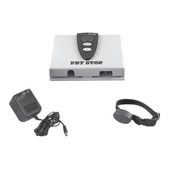
- Page 3 Owner’s Guide PCC-200 Transmitter AC Adapter Collar *May include wire, splices and fl ags (not pictured) Congratulations! You have purchased the most comfortable and reliable pet fencing system for your cherished family pet. system was designed by the industry’s Pet Stop Comfort Contact ™ most experienced team to provide years of worry-free freedom for both you and your pet. Simply follow the steps outlined in this user’s guide and your fence will be operational in no time. Should you have any diffi culty along the way, help is available by talking to a local Pet Stop Fencing Professional. ® www.petstop.com MKTG0715_063_E_Comfort Contact Owners Guid-PS.indd 1 7/21/15 12:26 PM...
- Page 4 Owner’s Guide PCC-200 Your new Pet Fencing System AT A GLANCE 1. Determine the layout of your fence The Comfort Contact Pet Fencing System is completely customizable to any shape of property and can be used to keep your pet away from off-limits areas such as gardens or pools. (See page 4 for sample layouts) Be sure to call your local utility companies to mark underground cables before you dig! 2. Select a transmitter location The wall-mount transmitter is your pet’s fence control center. The transmitter sends a digitally encoded radio signal through the fence wire. The transmitter needs to be located in a dry, indoors area such as a garage or utility room. 3. Lay out your fence wire Always lay your fence wire on top of the ground before burying to ensure the fence is performing properly.
- Page 5 Owner’s Guide PCC-200 Your new Pet Fencing System AT A GLANCE 5. System Adjustments Programming Options The Pet Stop Comfort Contact System (PCC-200) can be programmed for up to five different stimulation levels and two different frequency settings by following the easy programming steps (see page 9 for reference). 6. Bury fence wire The fence wire that dictates your pet’s boundaries is buried 1” – 3” under the ground. You can use a flat edge spade, gas powered edger or there may be Pet Stop Professional installation help avail- ® able in your area. 7. Training your pet Training your pet to her new fence will take approximately two weeks, with most of the time spent closely watching your pet to ensure compliance to the fencing system. MKTG0715_063_E_Comfort Contact Owners Guid-PS.indd 3 7/21/15 12:26 PM...
- Page 6 Owner’s Guide PCC-200 STEP 1 Planning your fence layout • When designing your fence layout, it is important to remember that your fence boundary is one continuous loop of wire, starting at your wall-mount trans- mitter, forming a boundary loop around your selected area and returning back to the transmitter. Entire Yard • You will need to allow room in your plan for 8’ – 10’ of signal area from the boundary wire. • Do not run the boundary wire within 10’ parallel of utility lines. Utility lines can create interference. Have utility lines marked prior to fence wire installation. • To maintain a consistent signal fi eld, Around Obstacles use a gradual radius when running the wire around corners, as illustrated. Avoid hard 90 degree angles. √ back Yard Only ×...
- Page 7 Owner’s Guide PCC-200 STEP 2 STEP 3 Selecting a transmitter location Lay out your fence & wire connections • Select a location to hang your system transmitter that is dry and indoors with It is important to lay out your boundary a standard 110VAC electrical outlet wire and test your fencing system before nearby. A location in the garage or util- you bury the wire. This is a real time saver ity room is usually ideal. should you encounter a problem with your installation. • When selecting a location, keep in mind that the fence system wire will run from 1. Measure the your transmitter to the wire boundary amount of outdoors. This can be done through a distance from window or by drilling a 3/8th inch hole your wall- at the base of the wall for the wire to mount trans- pass through.
- Page 8 Owner’s Guide PCC-200 3. Starting at the end of your twisted wire, 6. It is recommended that you ground run your single strand of wire around your transmitter. Connect the ground your property as you have designed, terminal (center screw wire connec- ending back again at the end of your tion) on the transmitter to a ground rod twisted wire. (via electrical wire) located outside of Boundary the house with ground rod material and Loop 4. Twist one end depth as recommended by the National of your bound- Electrical Code. To Transmitter ary loop to one end of the The alternative way is to connect the Twisted Wire twisted wire ground terminal on the transmitter with a wire to the center screw on the AC outlet Splice nut. Repeat via electrical wire (center screw is with the remaining loose ends. Using ground). The outlet used must be the waterproof splices, push each wire grounded to be effective. nut as far down into the gel as possible and secure lid. Check to ensure that An experienced pet fence dealer, tv...
- Page 9 Owner’s Guide PCC-200 STEP 4 5. Walk back and forth over the twisted wire listening for any warning beeps. Testing your fence operation There should be none. It is important to test that your system is 6. Walk around the “safe” areas of the functioning properly before burying the yard and house listening for any warn- boundary wire. You will be looking to en- ing beeps. Again, there should be no sure that the fence is activating properly response from the pet’s collar when at the boundary locations, as well as look- further than 10’ from the boundary loop. ing for unwanted signals in the house and other safe areas of the home. TROubLEShOOTING TIPS 1. Install the supplied battery in your pet’s The collar will not activate at the bound- training collar. Remove the battery ary loop: cover screw cap, insert the battery and ensure that the positive end is closest • T he training collar’s battery has been to the battery compartment open- installed in the proper orientation and ing. Replace the battery cap.
- Page 10 Owner’s Guide PCC-200 • Move the boundary loop away from You may encounter some obstacles that large metal objects such as outdoor will need to be crossed during your instal- sheds or metal fences. lation. • Move the boundary wire away from the • When crossing a concrete driveway, side of the house. clean out an expansion joint with a screwdriver, push wire into the slot and • Turn the signal strength down on the cover with a clear silicone caulk. wall-mount transmitter. (See STEP 6: System Adjustments and Programming) • It is necessary to cut a trench in asphalt driveways with a circular saw and masonry blade. Place wire in trench STEP 5 and cover with asphalt sealant. Burying the fence wire • The wire can be run through PVC tubing After you have or a garden hose and left on top of the the fence wire ground when crossing heavily wooded, positioned on rock areas or when crossing creeks or the top of the streams. The PVC or garden hose will...
- Page 11 Owner’s Guide PCC-200 STEP 6 Extra Light to high depending on your dog’s personality and temperament. To System adjustments change the system correction levels: and programming STEP 1 – Press Adjusting the Signal Field Width and hold both the top and PLEASE NOTE: The number displayed on bottom but- your wall-mount transmitter in its normal, SCROLL tons, marked active state is NOT ThE STRENGTh OF SCROLL and CORRECTION OR COLLAR OuTPuT. This SET on the wall number represents the signal field area. transmitter simultaneously The signal field setting determines the...
- Page 12 Owner’s Guide PCC-200 and is ready to be programmed. Press and to select desired frequency settings. The release the bottom button marked SET on transmitter display will show the corre- the wall transmitter. sponding number with each button push. The collar receiver light will flash the Settings number corresponding to the level you 01 = 7 KHz have selected. When programming is 02 = 4 KHz complete the transmitter will return auto- matically to normal operation. STEP 3 – Hold the pet fence collar receiver Radio Frequency Programming SCROLL This programming option allows the user against the to switch the operating frequency from 7 wall mount KHz to 4 KHz in the unlikely case of signal transmitter. interference from sources such as neigh- The collar boring pet fencing systems. Your system receiver light has come preset from the factory on 7 KHz will illuminate where you are most likely not to encoun- and is ready to be programmed. Press and ter interference issues.
- Page 13 Owner’s Guide PCC-200 STEP 7 LESSON 5: Off Lead Unsupervised 2 Weeks Training your pet LESSON 6: Flag Removal Please take your time training your dog every other day until gone and complete each step of the process to enjoy optimal performance from your sys- • Use a calendar so you can keep track tem. If you have questions along the way, of the training process. Your dog’s expert advice is only a call away. Please behavior will tell you when it is time to call your local Pet Stop Professional. proceed to the next level. The goal of fence training is to help you • A training session includes putting the teach your dog to identify and respect her Pet Stop training collar on your dog, new fence, to make the training fair—so making sure that the collar has the your dog will understand the consequenc- proper fit high on the dog’s neck and es of leaving and to make the training the collar is making contact with the...
- Page 14 Owner’s Guide PCC-200 LESSON 1 to anticipate the signal and retreat without your prompting. Back Away From the Fence! Day three is successful if your dog Start the first retreats without your prompting and phase of train- refuses to approach the boundary as you ing with the approach. For each successful attempt be collar contacts sure to praise, praise and praise again. covered with the supplied LESSON 2 post cov- ers that are Respect the Fence included with your Pet Stop Fence. This is to ensure that Although your dog is learning fast and your dog can hear the warning tone at the avoiding the boundary, he will forget boundary, but there is no chance of cor- or attempt to break the rules with an rection. The post covers will be removed interesting distraction beyond your yard. in phase 2 of the training. To prevent this, your dog must experience what happens if the fence boundaries are Put the...
- Page 15 Owner’s Guide PCC-200 LESSON 4 Should your dog not appear Off Lead With Supervision to have felt the collar cor- After several sessions of distractions, rection, check your dog should be ready for off lead to ensure the play. You must stay in the yard for off lead collar is making training. contact with the skin. It may The more your dog stays on the property be necessary to use one of the longer for the first month, the less chance of your metal contacts provided for dogs with a dog ever attempting to leave the area. dense coat. Continue to supervise and play with your LESSON 3 dog outside for a period of one week. Distractions Should your dog bolt out of the property for any reason during this phase, retrace If your dog is avoiding the boundary at your last training steps with distractions multiple locations around your boundary, with your dog on a leash. you are ready to add more tempting dis- tractions. Remember, never pull or coax LESSON 5 your dog into the boundary area.
- Page 16 Owner’s Guide PCC-200 LESSON 6 Removing the Flags After two weeks of successful contain- ment, you can begin removing the flags. Start by removing every other flag, every other day, until all of the flags are gone. The leads, trainers, flags and the elec- tronic training collar are all clues for your dog to learn the boundaries. They are all removed gradually except the electronic training collar. It’s essential that you observe whether your off lead, unsupervised dog still avoids and retreats from the unmarked bound- ary. If your dog’s response is anything but immediate retrace your steps through the training process. Thank you for choosing Pet Stop. MKTG0715_063_E_Comfort Contact Owners Guid-PS.indd 14 7/21/15 12:26 PM...
- Page 17 Owner’s Guide PCC-200 TRAINING AND INSTALLATION NOTES: MKTG0715_063_E_Comfort Contact Owners Guid-PS.indd 15 7/21/15 12:26 PM...
- Page 18 Owner’s Guide PCC-200 TRAINING AND INSTALLATION NOTES: MKTG0715_063_E_Comfort Contact Owners Guid-PS.indd 16 7/21/15 12:26 PM...
- Page 19 Call Your Local Pet Stop Professional First. We Can Help. Pet Stop warrants that its products to the original retail purchaser will be free from defects in material and workmanship, under normal use, for a period of one year from the date of the original retail purchase at no cost. Shipping to repair center not included. This coverage does not include accidental damage or misuse. After one year from date of original consumer purchase, Pet Stop will, at our option, repair, replace or upgrade the defective component at a fixed rate based on the component, for the life of the original owner. Owner must provide proof of purchase. Cost of shipping is not covered under the warranty. Some shipping charges may apply. Pet Stop offers a hassle-free replacement program. Simply call your Pet Stop Professional and let us help you with your problem. MKTG0715_063_E_Comfort Contact Owners Guid-PS.indd 17 7/21/15 12:26 PM...
- Page 20 Perimeter Technologies, Inc. Reading, PA 19606 1-866-900-2007 www.petstop.com ©2015 Perimeter Technologies, Inc. All rights reserved. Our products are covered by U.S. Patent Numbers: 5,460,124 - 5,682,839 - 6,296,776 MKTG0715.063 MKTG0715_063_E_Comfort Contact Owners Guid-PS.indd 18 7/21/15 12:26 PM...
Need help?
Do you have a question about the Comfort Contact PCC-200 and is the answer not in the manual?
Questions and answers
que alcance maximo de cable puede ser