Table of Contents
Advertisement
Advertisement
Chapters
Table of Contents

Related Manuals for Kinco N Series


Summary of Contents for Kinco N Series
- Page 1 N 系列步进驱动器 Kinco ® 2M1180N/2M2280N 使用说明书 版本:V1.3...
-
Page 3: Table Of Contents
2M1180N/2M2280N 步进驱动器 目 录 第一章 安全事项 ......................2 第二章 产品概述 ......................3 2.1 产品确认 ........................3 2.2 产品型号说明 ......................3 2.3 产品概述 ........................3 2.4 产品特点 ........................3 2.5 产品功能 ........................4 2.6 应用领域 ........................4 第三章 产品参数与安装 .....................5 3.1 产品参数 ........................5 3.2 接线端子说明 ......................5 3.3 接线图示 ........................6 3.4 控制信号时序图... -
Page 4: 第一章 安全事项
使用手册 第一章 安全事项 为了避免人身伤害和财产损失,请在调试及使用驱动器前仔细阅读以下安全信息。 以下安全措施必须严格遵守: 仔细阅读产品使用手册。 严格遵守安全守则。 2M2280N 驱动器正常工作时内部将有 300VDC 左右的高压,2M1180N 驱动器在正常工 作时内部将有 150VDC 左右的高压,在切断驱动器电源 60 秒内,驱动器仍然存在高压, 请等驱动器的电压降到安全范围内,再进行接线或检查,否则可能遭到电击。 请勿在驱动器及电机工作时进行接线,否则可能遭到电击。 请勿在通电后或驱动器运行时拆开驱动器外壳,否则可能遭到电击。 为了避免人身伤害和财产损失,只有具有相关专业知识的人员才可以对驱动器进行操 作。 安装过程中请遵守相关技术规范和电气安装标准。必须把驱动器良好地接地,接地电缆 的截面积不小于 1.25 毫米。 请不要把任何物体放入驱动器内,否则可能造成驱动器损坏。 驱动器出现故障需要检修时,请将驱动器送回检修中心。私自打开驱动器或不正确的操 作会损坏驱动器。未经允许,私自打开驱动器外壳的情况下保修作废。 在废弃驱动器的时候,请按照工业废弃物的标准来处理,以免造成环境的污染。 声明:... -
Page 5: 第二章 产品概述
2M1180N/2M2280N 步进驱动器 第二章 产品概述 2.1 产品确认 收到产品后,请仔细核对以下项目: 请确认驱动器型号与订购的型号是否一致。 打开产品包装后,请确认产品有无损坏或缺少零件等异常情况。 请确认驱动器上所有固定螺丝都是牢固的。 请按产品清单核对您收到的产品,如有缺少请及时联系我公司客服人员。 产品清单 物品 数量 2M2280N 驱动器或 2M1180N 驱动器 1 台 产品服务指南 1 张 驱动器使用手册 1 本 合格证 1 张 2kΩ 金属膜插件电阻 3 个 长 10mm 直径φ 10 绝缘端子 4 个... -
Page 6: 产品功能
过压报警功能:2M2280N 驱动器会在内部母线电压超过 395VDC 的时候, 2M1180N 驱 支会在内部母线电压超过 187VDC 的时候,进入高压报警状态。此时应及时切断电源, 重新启动驱动器可清除此报警。如果频繁出现过压报警,建议调低输入电压,或采用带 吸收功能的驱动器。 过流报警功能:在电机或驱动器出现短路,接错线等情况下,驱动器会产生过流保护, 以免意外情况下的大电流损坏驱动器,出现过流报警时应及时切断电源,并检查电机的 接线。重新启动驱动器可清除此报警。 欠压报警功能:2M2280N 驱动器在内部母线电压低于 200VDC 的时候,2M1180N 驱动 器在内部母线电压低于 90VDC 的时候,驱动器进入欠压报警状态,欠压报警时重新启 动驱动器可以消除此报警。 过热报警功能:驱动器会在其内部温度达到 75 度时,进入过热报警状态。 错相保护功能:当驱动器与电机间的连线出错时,驱动器会进入错相报警状态,重新按 符合要求的接线方式接线,可以清除此报警。 2.6 应用领域 适合各种大中型自动化设备和仪器,如雕刻机,贴标机,切割机,数控机床,绘图仪等, 是要求实现低振动,小噪声,高精度,高速度的用户的理想选择。 推荐配套使用 KINCO 系列 110 及 130 型步进电机,以达到最佳控制效果。... -
Page 7: 第三章 产品参数与安装
2M1180N/2M2280N 步进驱动器 第三章 产品参数与安装 3.1 产品参数 在使用驱动器前,请务必详细了解驱动器参数,并确保驱动器工作在符合要求的供电环 境与应用环境中! 表 1 驱动器电气参数表 参数 描述 2M2280N:单相交流 220V AC +/-15%(50Hz) (187VAC~253VAC) 输入电压 2M1180N:单相交流 77V AC~123VAC, (50Hz) 相电流(峰值) 4.5A,5A,5.5A,6A,6.5A,7A,7.5A,8A 共 8 档 细分档 2/4/5/8/10/16/20/32/50/64/100/128, 共 12 档 适用电机 110,130 型步进电机 输入信号 PLS (CW) /DIR (CCW) /FRE 三个控制信号端口, 电流范围为:6~16 mA 信号输入方式... -
Page 8: 接线图示
使用手册 在单脉冲模式下,此信号为方向控制信号,驱动器通过检测此信号的电 DIR+ (CCW+) 平设置电机运转方向。此信号有效值为脉冲信号上升沿时刻。 在双脉冲模式下,此信号为反转控制信号,上升沿有效。 DIR- 为了保证内部光耦的可靠响应,双脉冲高电平时间应不小于 1.25uS。 (CCW-) 脉冲信号的最高输入频率为 400KHz 此信号为脱机信号,此信号为高电平时,驱动器切断电机供电,电机转 FREE+ 子处于自由状态(脱机) 。 FREE- 报警输出信号。此信号端口为集电极开路的光耦输出,当驱动器出现异 ERR+ 常报警或断电时,此信号端口的光耦无输出(电平由外接电路决定) 。 ERR- 端口最大允许输入电压为 30VDC,最大供电电流为 10mA。 表 4 强电端口定义 信号 功能描述 电机 A 相接入口。A+,A-互换可改变电机方向。 电机 B 相接入口。B+,B-互换可改变电机方向。 吸收(刹车)电阻接入口。 表 5 电源输入端口定义 驱动器电源输入接口,2M2280N 驱动器允许直接接入单相... - Page 9 2M1180N/2M2280N 步进驱动器 控制信号双绞方式接法 驱动器的所有控制信号的输入电路中都采用了可靠的光耦元件进行隔离,可以减少外部 电气噪声对于本驱动器的干扰。 图中 R0 为外部限流电阻,用于限制驱动器的输入信号电流,在控制信号为 24VDC 时, 可接入 2K 的电阻,如果控制信号为 12VDC 时,则可接入 1K 的电阻,必须保证驱动器 的输入口电流在 6~16mA 范围, 否则电流过小可能会使信号失效,电流过大会损坏设备。 ERR 信号为集电极开路输入,输要外接电源,最大外接电压不超过 30V。ERR 信号端口 严禁将电源反接,否则会损坏端口。 如果现场应用有较强干扰时, 控制信号推荐用双绞方式接线,以减少干扰源对控制信号的 干扰。...
-
Page 10: 控制信号时序图
使用手册 3.4 控制信号时序图 控制信号注意事项: 输入脉冲的最高频率为 400KHz。 方向信号禁止在脉冲信号上升期间变化。 脱机信号必须提前脉冲信号 1ms 建立。 驱动器接线注意事项: 驱动器布线时,为了避免驱动器受到干扰,请遵循强电(电机相线与电源线)与弱电隔 离布线的原则(最少要相距 10 厘米) 。 驱动器的控制信号接线建议采用屏蔽双绞线,屏蔽层必须可靠接地(驱动器与设备的真 实地) 。 驱动器的电机动力线及电源线由于要承受较大的电流,因此建议使用的导体截面积不小 于 1.5mm ,必要时视电流大小选用更大截面积的导线。 严禁带电接拨线,否则可能造成设备损坏及人身伤害。特别注意电机在锁紧状态,电机 动力线上仍然具有较大的电流,强行接拔线会造成设备损坏及人身伤害。 电机动力线及驱动器电源输入线接入端子的裸线长度应为 10mm 左右,裸线太短会造成 接触不良,裸线太长有电击危险。电机动力线套上绝缘端子,可减小与端子的接触电阻。... -
Page 11: 拨码开关设置
2M1180N/2M2280N 步进驱动器 3.5 拨码开关设置 驱动器共配置有两个圆型拨码开关 S1、S2,实现驱动器的细分选择,电流值选择,试运 行状态使能及单/双脉冲控制信号选择。 S1,Micro-step:细分与试运行功能选择开关 Micro step Pulse/rev 1000 1600 2000 3200 4000 6400 Micro step TEST Pulse/rev 10000 12800 20000 25600 S2,Current:电流与单双脉冲选择开关 Mode PLS+DIR Rms(A) 3.18 3.54 3.89 4.24 4.60 4.95 5.30 5.65 Peak(A) Mode CW/CCW Rms(A) 5.65 5.30... -
Page 12: 驱动器的安装
使用手册 3.6 驱动器的安装 安装注意事项: 建议将驱动器正立侧面安装,以保证驱动器的安装环境通风顺畅,特别是驱动器的通风 口,绝不能有遮盖物,否则会使驱动器频繁过热报警而影响正常使用。 为保证驱动器的良好散热,两台驱动器之间的安装距离应不少于 50mm。 本驱动器的防护等级为 IP20,请将驱动器置于符合要求的室内环境及电气柜中运行,否 则可能导致驱动损坏及人身伤害。 当驱动器频繁出现过热报警时,表示需要对驱动器进行加强散热,可在靠近驱动器处安 装风扇,强制冷却散热,以确保驱动器在可靠的工作温度范围内工作。 ... -
Page 13: 第四章 常见问题及解答
2M1180N/2M2280N 步进驱动器 第四章 常见问题及解答 4.1 驱动器指示灯显示指南 N 系列步进驱动器拥有完善的保护电路,最大限度地确保驱动器的安全。同时,丰富的指 示灯状态指示,使你能够时刻掌握驱动器的工作状态! 指示灯状态定义: 指示灯 报警 解决办法 Power Error Chop 内部不通电 熄灭 熄灭 熄灭 熄灭 检查电源 单片机复位 开启 开启 开启 开启 硬件出错 开启 熄灭 开启 开启 检查电机接线 电机相间出错 开启 熄灭 开启 快闪 检查电机接线 过流报警 开启... - Page 14 为全球客户提供中国人的自动化解决方案 深圳市步科电气有限公司 Kinco Electric (Shenzhen) Ltd. 地 址:深圳市南山区高新科技园北区朗山一路 6 号一栋(518057) 电 话:86-755-26585555 传 真:86-755-26616372 http://www.kinco.cn Email: sales@kinco.cn...
- Page 15 ® Kinco N Series Stepper Motor Driver 2M1180N/2M2280N User Manual Version: V1.33...
- Page 17 Chapter 4 FAQ................................15 4.1 Indications of Driver Indicators ........................15 4.2 FAQ on the Driver and Stepper Motor .......................16 Release Notes on N Series Multi-functional Micro-step Stepper Motor Driver User Manual Products involved: 2M2280N and 2M1180N stepper motor drivers.
-
Page 18: Chapter 1 Safety Precautions
User Manual Chapter 1 Safety Precautions For the sake of personal safety and avoidance of property loss, please read these safety precautions carefully before test running and use of the driver. The following safety measures must be strictly followed: Read this user manual carefully. ... -
Page 19: Chapter 2 Product Overview
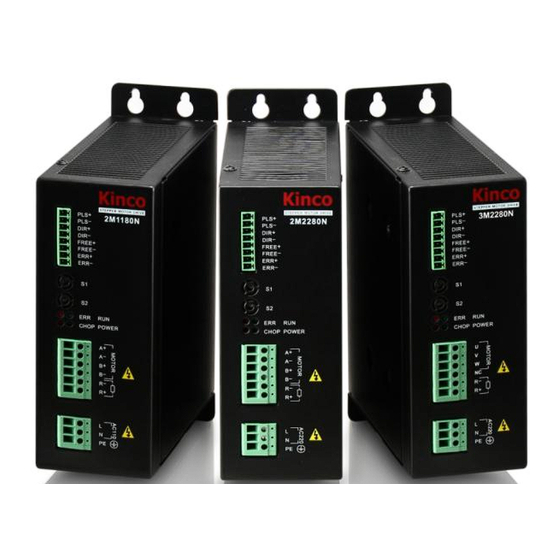
2.2 Product Model Description 2.3 Product Overview N series drivers are the latest high-subdivision stepper motor drivers launched by Kinco Electric (Shenzhen) Ltd. With the DSP single-chip microcomputer as the control core, these products adopt vector current control algorithm and are suitable for driving 2-phase hybrid stepper motors under various brand names. -
Page 20: Product Features
User Manual 2.4 Product Features High performance, low cost, and diversified functions. 2M2280N adopts 187V~253V wide-range power supply and can be connected directly with single-phase 220V AC power to save the cost of a transformer. Automatic parameter adjustable regulation. ... -
Page 21: Scope Of Application
They are ideal choices for users in search of low vibration, low noise, high accuracy, and high speed. To achieve the optimum performance, KINCO 110 and 130 series stepper motors are recommended. -
Page 22: Chapter 3 Product Parameters And Installation
User Manual Chapter 3 Product Parameters and Installation 3.1 Product Parameters Please learn carefully the driver parameters before use. Make sure the power supply and operating environment conform to relevant requirements. Table 1 Electrical Specifications Parameter Description Input voltage 2M2280N: Single-phase 220V AC +/-15% (50Hz)(187VAC~253VAC) 2M1180N: Single-phase 77V AC~123VAC, (50Hz) Phase 4.5A,5A,5.5A,6A,6.5A,7A,7.5A,8A... - Page 23 2M1180N/2M2280N Stepper Motor Driver Table 3 Definition of Control Signal Port Signal Functional Description PLS+(CW+) Pulse signal. In the PLS+DIR control signal mode, the signal is the pulse control signal and the rising edge is effective. In the CW/CCW control signal mode, the signal is the forward rotation PLS-(CW-) control signal and the rising edge is effective.
-
Page 24: Wiring Diagram
User Manual Table 4 Definition of Strong Current Port Signal Functional Description Phase A of motor. The switching between A+ and A- can change motor rotation direction. Phase B of motor. The switching between B+ and B- can change motor rotation direction. Absorbing(Break)resistor port. - Page 25 2M1180N/2M2280N Stepper Motor Driver Twisted-pair Way Control Signal Wiring Diagram The input circuits of all control signals of the driver have been reliably isolated through optocoupler elements, which minimize the interference from external electrical noises. In the figure, R0 is an external current limit resistor used to curb the input si gnal ...
-
Page 26: Time Sequence Diagram Of Control Signal
User Manual 3.4 Time Sequence Diagram of Control Signal Precautions on Control Signal: The maximum frequency of the input pulse is 400 KHz. Disable direction signal change during pulse signal rise time. An offline signal shall be set ... -
Page 27: Dip Switch Settings
2M1180N/2M2280N Stepper Motor Driver 3.5 DIP Switch Settings The driver is configured with two round DIP switches S1 and S2, which are used for macro-step value selection, current value selection, test running status enabling, and PLS+DIR or CW/CCW control signal selection. S1,Micro-step: Micro step Pulse/rev... - Page 28 User Manual Precautions on rotary switch: S1 cannot be set to NA; otherwise, the driver will generate an alarm. In this case, turn off the power, re-set the macro-step values, and turn on the power again to resume normal. ...
-
Page 29: Installation Of The Driver
2M1180N/2M2280N Stepper Motor Driver 3.6 Installation of the driver If the field application need motor response speed very very high, such as digital control machine application,it recommend to disable mircro-step smoothing filter to reduce the time of motor reach the location。 Precautions on Installation: It is recommended that the driver be mounted on a side and kept in an upright ... - Page 30 User Manual frequently. A fan may be installed in a position close to the driver for forced cooling and heat dissipation, so as to ensure the driver works in an allowable temperature range。...
-
Page 31: Chapter 4 Faq
Chapter 4 4.1Indications of Driver Indicators N series stepper motor drivers are equipped with complete protection circuits to protect their safety to the greatest extent possible. In addition, the rich indications of indicators help the user to learn the working status of the driver in time. -
Page 32: Faq On The Driver And Stepper Motor
User Manual Note: Blinking slowly means blinking at a frequency of 0.5 Hz, and blinking quickly means blinking at a frequency of 5Hz. To clear any alarm of the driver, it is necessary to disconnect the power supply and ... - Page 36 To be the partner of your success Kinco Electric (Shenzhen) Ltd. Address:Building1, No.6 Langshan 1st Rd, Hi-tech Park North, Nanshan, Shenzhen, China. 518057 Tel: 86-755-26585555 Fax: 86-755-26616372 http://www.kinco.cn Email:sales@kinco.cn...
Need help?
Do you have a question about the N Series and is the answer not in the manual?
Questions and answers